

466
K.B. Katsaros
Sub-Satellite Track
s ... u h ot AM I
:,,--.SAR Wave Mode
~
(lOKm x Skml
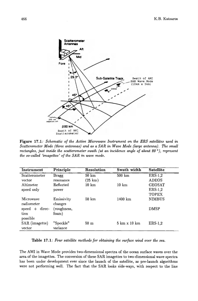
Figure 17.1: Schematic of the Active Microwave Instrument on the ERS satellites used in
Scatterometer Mode (three antennas) and as a SAR in Wave Mode (large antenna). The small
rectangles, just inside the scatterometer swath (at an incidence angle of about 20 O), represent
the so-called 'imagettes' of the SAR in wave mode.
Instrument
Principle
Scatterometer
Bragg
vector
resonance
Altimeter
Reflected
speed only
power
Microwave
Emissivity
radiometer
changes
speed + direc- (roughness,
tion
foam)
possible
SAR (imagette) "Speckle"
vector
varIance
Resolution
50 km
(25 km)
10 km
50 km
50 m
Swath width
500 km
10 km
1400 km
5 km x 10 km
Satellite
ERS-1,2
ADEOS
GEOSAT
ERS-1,2
TOPEX
NIMBUS
DMSP
ERS-1,2
Table 17.1: Four satellite methods for obtaining the surface wind over the sea.
The AMI in Wave Mode provides two-dimensional spectra of the ocean surface waves over the
area of the imagettes. The conversion of these SAR imagettes to two-dimensional wave spectra
has been under development ever since the launch of the satellite, as pre-launch algorithms
were not performing well. The fact that the SAR looks side-ways, with respect to the line
K.B. Katsaros
Sub-Satellite Track
s ... u h ot AM I
:,,--.SAR Wave Mode
~
(lOKm x Skml
Figure 17.1: Schematic of the Active Microwave Instrument on the ERS satellites used in
Scatterometer Mode (three antennas) and as a SAR in Wave Mode (large antenna). The small
rectangles, just inside the scatterometer swath (at an incidence angle of about 20 O), represent
the so-called 'imagettes' of the SAR in wave mode.
Instrument
Principle
Scatterometer
Bragg
vector
resonance
Altimeter
Reflected
speed only
power
Microwave
Emissivity
radiometer
changes
speed + direc- (roughness,
tion
foam)
possible
SAR (imagette) "Speckle"
vector
varIance
Resolution
50 km
(25 km)
10 km
50 km
50 m
Swath width
500 km
10 km
1400 km
5 km x 10 km
Satellite
ERS-1,2
ADEOS
GEOSAT
ERS-1,2
TOPEX
NIMBUS
DMSP
ERS-1,2
Table 17.1: Four satellite methods for obtaining the surface wind over the sea.
The AMI in Wave Mode provides two-dimensional spectra of the ocean surface waves over the
area of the imagettes. The conversion of these SAR imagettes to two-dimensional wave spectra
has been under development ever since the launch of the satellite, as pre-launch algorithms
were not performing well. The fact that the SAR looks side-ways, with respect to the line