

2.4 Components of a Numerical Solution Method
27
grid points: concentration of points in one region for reasons of accuracy
produces unnecessarily small spacing in other parts of the solution domain
and a waste of resources. This problem is exaggerated in 3D problems. The
long thin cells may also affect the convergence adversely.
Structured grids may be of H-, 0 - , or C-type; the names are derived
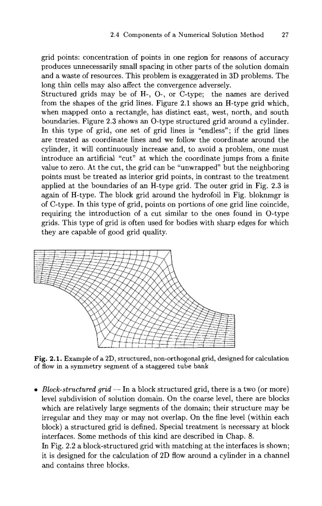
from the shapes of the grid lines. Figure 2.1 shows an H-type grid which,
when mapped onto a rectangle, has distinct east, west, north, and south
boundaries. Figure 2.3 shows an 0-type structured grid around a cylinder.
In this type of grid, one set of grid lines is "endless"; if the grid lines
are treated as coordinate lines and we follow the coordinate around the
cylinder, it will continuously increase and, to avoid a problem, one must
introduce an artificial "cut" a t which the coordinate jumps from a finite
value to zero. At the cut, the grid can be "unwrapped" but the neighboring
points must be treated as interior grid points, in contrast to the treatment
applied at the boundaries of an H-type grid. The outer grid in Fig. 2.3 is
again of H-type. The block grid around the hydrofoil in Fig. bloknmgr is
of C-type. In this type of grid, points on portions of one grid line coincide,
requiring the introduction of a cut similar to the ones found in 0-type
grids. This type of grid is often used for bodies with sharp edges for which
they are capable of good grid quality.
Fig. 2.1. Example of a 2D, structured, non-orthogonal grid, designed for calculation
of flow in a symmetry segment of a staggered tube bank
0 Block-structured grid - In a block structured grid, there is a two (or more)
level subdivision of solution domain. On the coarse level, there are blocks
which are relatively large segments of the domain; their structure may be
irregular and they may or may not overlap. On the fine level (within each
block) a structured grid is defined. Special treatment is necessary a t block
interfaces. Some methods of this kind are described in Chap. 8.
In Fig. 2.2 a block-structured grid with matching at the interfaces is shown;
it is designed for the calculation of 2D flow around a cylinder in a channel
and contains three blocks.
27
grid points: concentration of points in one region for reasons of accuracy
produces unnecessarily small spacing in other parts of the solution domain
and a waste of resources. This problem is exaggerated in 3D problems. The
long thin cells may also affect the convergence adversely.
Structured grids may be of H-, 0 - , or C-type; the names are derived
from the shapes of the grid lines. Figure 2.1 shows an H-type grid which,
when mapped onto a rectangle, has distinct east, west, north, and south
boundaries. Figure 2.3 shows an 0-type structured grid around a cylinder.
In this type of grid, one set of grid lines is "endless"; if the grid lines
are treated as coordinate lines and we follow the coordinate around the
cylinder, it will continuously increase and, to avoid a problem, one must
introduce an artificial "cut" a t which the coordinate jumps from a finite
value to zero. At the cut, the grid can be "unwrapped" but the neighboring
points must be treated as interior grid points, in contrast to the treatment
applied at the boundaries of an H-type grid. The outer grid in Fig. 2.3 is
again of H-type. The block grid around the hydrofoil in Fig. bloknmgr is
of C-type. In this type of grid, points on portions of one grid line coincide,
requiring the introduction of a cut similar to the ones found in 0-type
grids. This type of grid is often used for bodies with sharp edges for which
they are capable of good grid quality.
Fig. 2.1. Example of a 2D, structured, non-orthogonal grid, designed for calculation
of flow in a symmetry segment of a staggered tube bank
0 Block-structured grid - In a block structured grid, there is a two (or more)
level subdivision of solution domain. On the coarse level, there are blocks
which are relatively large segments of the domain; their structure may be
irregular and they may or may not overlap. On the fine level (within each
block) a structured grid is defined. Special treatment is necessary a t block
interfaces. Some methods of this kind are described in Chap. 8.
In Fig. 2.2 a block-structured grid with matching at the interfaces is shown;
it is designed for the calculation of 2D flow around a cylinder in a channel
and contains three blocks.