

380
12. Special Topics
mains in the CV, it becomes the material derivative and the CV becomes a
control mass.
Since solutions from previous time steps are not needed to compute surface and volume integrals, the grid can not only move but may also change
its topology, i.e. both the number of CVs and their shape can change from
one time step to another. The only term in which the old solution appears is
the unsteady term, which requires that volume integrals over the new CV of
some old quantities have to be approximated. If midpoint rule is used for this
purpose, all we need to do is to interpolate the old solutions to the locations
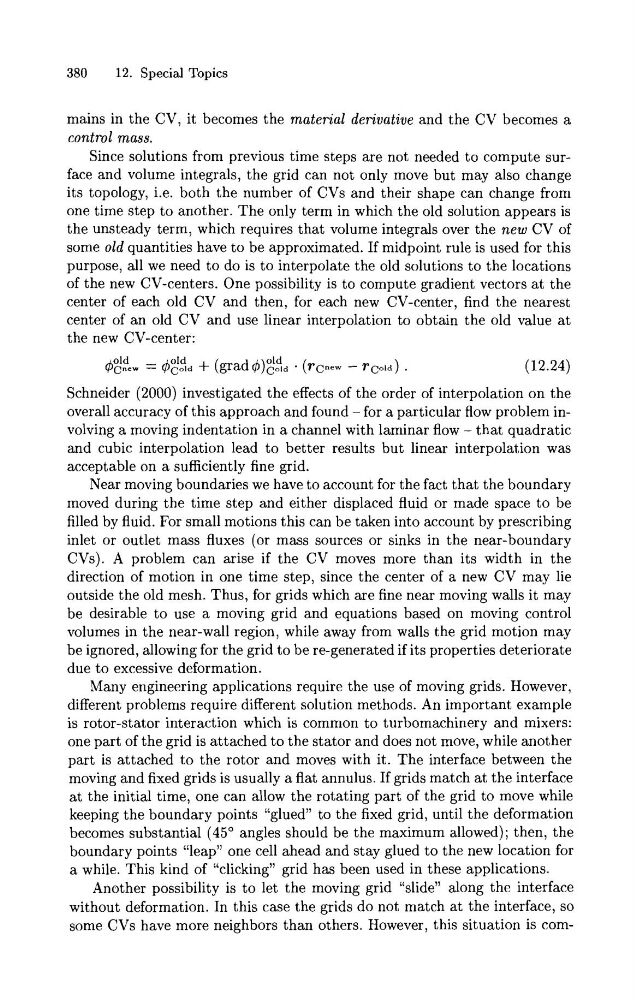
of the new CV-centers. One possibility is to compute gradient vectors at the
center of each old CV and then, for each new CV-center, find the nearest
center of an old CV and use linear interpolation to obtain the old value a t
the new CV-center:
Schneider (2000) investigated the effects of the order of interpolation on the
overall accuracy of this approach and found -for a particular flow problem involving a moving indentation in a channel with laminar flow - that quadratic
and cubic interpolation lead to better results but linear interpolation was
acceptable on a sufficiently fine grid.
Near moving boundaries we have to account for the fact that the boundary
moved during the time step and either displaced fluid or made space to be
filled by fluid. For small motions this can be taken into account by prescribing
inlet or outlet mass fluxes (or mass sources or sinks in the near-boundary
CVs). A problem can arise if the CV moves more than its width in the
direction of motion in one time step, since the center of a new CV may lie
outside the old mesh. Thus, for grids which are fine near moving walls it may
be desirable to use a moving grid and equations based on moving control
volumes in the near-wall region, while away from walls the grid motion may
be ignored, allowing for the grid to be re-generated if its properties deteriorate
due to excessive deformation.
Many engineering applications require the use of moving grids. However,
different problems require different solution methods. An important example
is rotor-stator interaction which is common to turbomachinery and mixers:
one part of the grid is attached to the stator and does not move, while another
part is attached to the rotor and moves with it. The interface between the
moving and fixed grids is usually a flat annulus. If grids match at the interface
a t the initial time, one can allow the rotating part of the grid to move while
keeping the boundary points "glued" to the fixed grid, until the deformation
becomes substantial (45" angles should be the maximum allowed); then, the
boundary points "leap" one cell ahead and stay glued to the new location for
a while. This kind of "clicking" grid has been used in these applications.
Another possibility is to let the moving grid "slide" along the interface
without deformation. In this case the grids do not match at the interface, so
some CVs have more neighbors than others. However, this situation is com-
12. Special Topics
mains in the CV, it becomes the material derivative and the CV becomes a
control mass.
Since solutions from previous time steps are not needed to compute surface and volume integrals, the grid can not only move but may also change
its topology, i.e. both the number of CVs and their shape can change from
one time step to another. The only term in which the old solution appears is
the unsteady term, which requires that volume integrals over the new CV of
some old quantities have to be approximated. If midpoint rule is used for this
purpose, all we need to do is to interpolate the old solutions to the locations
of the new CV-centers. One possibility is to compute gradient vectors at the
center of each old CV and then, for each new CV-center, find the nearest
center of an old CV and use linear interpolation to obtain the old value a t
the new CV-center:
Schneider (2000) investigated the effects of the order of interpolation on the
overall accuracy of this approach and found -for a particular flow problem involving a moving indentation in a channel with laminar flow - that quadratic
and cubic interpolation lead to better results but linear interpolation was
acceptable on a sufficiently fine grid.
Near moving boundaries we have to account for the fact that the boundary
moved during the time step and either displaced fluid or made space to be
filled by fluid. For small motions this can be taken into account by prescribing
inlet or outlet mass fluxes (or mass sources or sinks in the near-boundary
CVs). A problem can arise if the CV moves more than its width in the
direction of motion in one time step, since the center of a new CV may lie
outside the old mesh. Thus, for grids which are fine near moving walls it may
be desirable to use a moving grid and equations based on moving control
volumes in the near-wall region, while away from walls the grid motion may
be ignored, allowing for the grid to be re-generated if its properties deteriorate
due to excessive deformation.
Many engineering applications require the use of moving grids. However,
different problems require different solution methods. An important example
is rotor-stator interaction which is common to turbomachinery and mixers:
one part of the grid is attached to the stator and does not move, while another
part is attached to the rotor and moves with it. The interface between the
moving and fixed grids is usually a flat annulus. If grids match at the interface
a t the initial time, one can allow the rotating part of the grid to move while
keeping the boundary points "glued" to the fixed grid, until the deformation
becomes substantial (45" angles should be the maximum allowed); then, the
boundary points "leap" one cell ahead and stay glued to the new location for
a while. This kind of "clicking" grid has been used in these applications.
Another possibility is to let the moving grid "slide" along the interface
without deformation. In this case the grids do not match at the interface, so
some CVs have more neighbors than others. However, this situation is com-