

388
H. Okayama and J. Sun
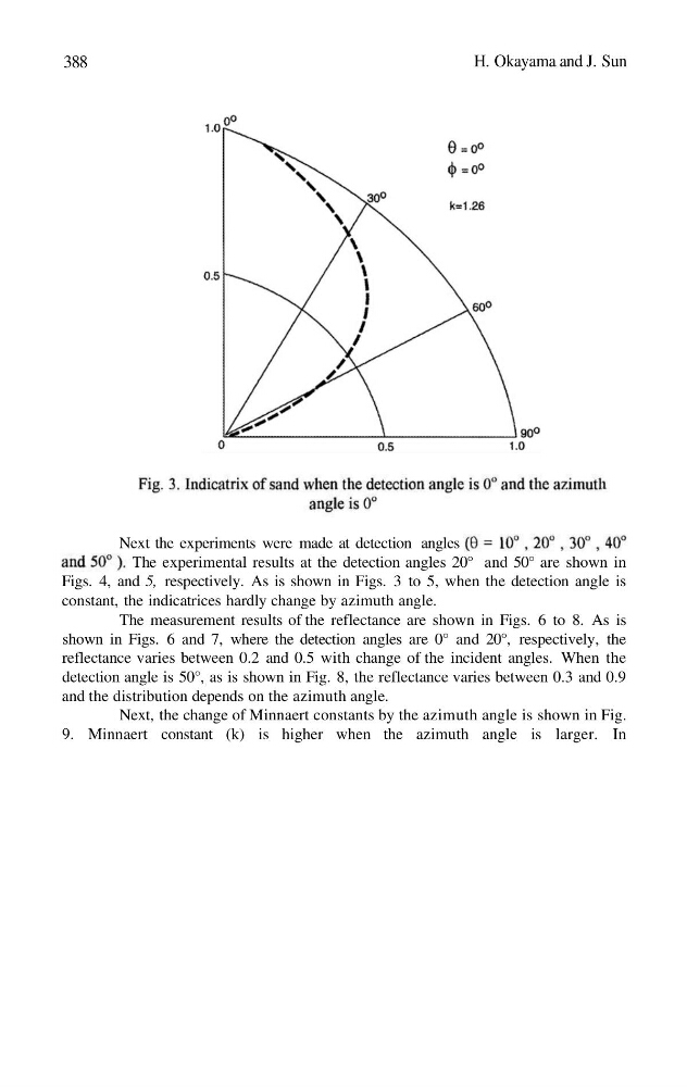
Next the experiments were made at detection angles
The experimental results at the detection angles 20° and 50° are shown in
Figs. 4, and 5, respectively. As is shown in Figs. 3 to 5, when the detection angle is
constant, the indicatrices hardly change by azimuth angle.
The measurement results of the reflectance are shown in Figs. 6 to 8. As is
shown in Figs. 6 and 7, where the detection angles are 0° and 20°, respectively, the
reflectance varies between 0.2 and 0.5 with change of the incident angles. When the
detection angle is 50°, as is shown in Fig. 8, the reflectance varies between 0.3 and 0.9
and the distribution depends on the azimuth angle.
Next, the change of Minnaert constants by the azimuth angle is shown in Fig.
9. Minnaert constant (k) is higher when the azimuth angle is larger. In
H. Okayama and J. Sun
Next the experiments were made at detection angles
The experimental results at the detection angles 20° and 50° are shown in
Figs. 4, and 5, respectively. As is shown in Figs. 3 to 5, when the detection angle is
constant, the indicatrices hardly change by azimuth angle.
The measurement results of the reflectance are shown in Figs. 6 to 8. As is
shown in Figs. 6 and 7, where the detection angles are 0° and 20°, respectively, the
reflectance varies between 0.2 and 0.5 with change of the incident angles. When the
detection angle is 50°, as is shown in Fig. 8, the reflectance varies between 0.3 and 0.9
and the distribution depends on the azimuth angle.
Next, the change of Minnaert constants by the azimuth angle is shown in Fig.
9. Minnaert constant (k) is higher when the azimuth angle is larger. In