

402
/. Wang et al.
et al. 1995). On-line measurement of Hg speciation may be a superior tool for
understanding the reaction kinetics and mechanisms involved, especially in flue
gas cleaning control. This chapter describes further work applying the on-line
method to a pilot-scale combustion simulator (Lindqvist and Schager 1990; Hall
1992) under controlled conditions, and to the Savenas MSWI plant in Goteborg,
providing a real industrial case study. Results obtained from these investigations
are presented and discussed.
2
Experimental
2.1
The Flue Gas Simulator
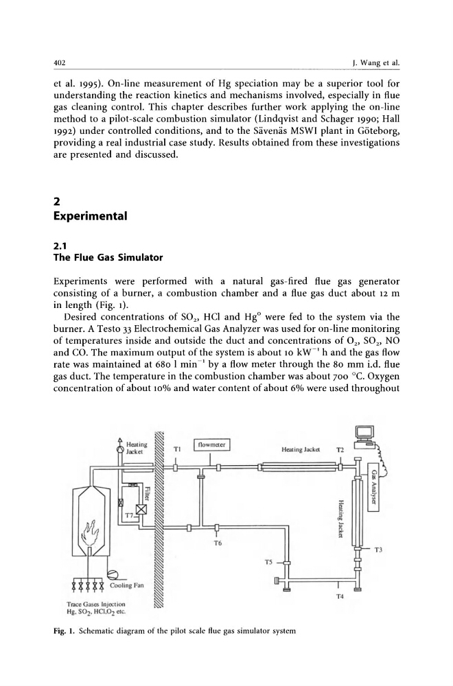
Experiments were performed with a natural gas-fired flue gas generator
consisting of a burner, a combustion chamber and a flue gas duct about 12 m
in length (Fig. 1).
Desired concentrations of S02' HCI and HgO were fed to the system via the
burner. A Testo 33 Electrochemical Gas Analyzer was used for on-line monitoring
of temperatures inside and outside the duct and concentrations of O2, S02' NO
and CO. The maximum output of the system is about 10 kW1
h and the gas flow
rate was maintained at 680 I min- I by a flow meter through the 80 mm i.d. flue
gas duct. The temperature in the combustion chamber was about 700 °C. Oxygen
concentration of about 10% and water content of about 6% were used throughout
Trace Oases Injection
Hg. S02. HCJ.02 elc.
T6
Healing Jack"
T5
Fig. I. Schematic diagram of the pilot scale flue gas simulator system
»
ill
J:
t
!oJ
5·
.. if ,..
11
T3
T4
/. Wang et al.
et al. 1995). On-line measurement of Hg speciation may be a superior tool for
understanding the reaction kinetics and mechanisms involved, especially in flue
gas cleaning control. This chapter describes further work applying the on-line
method to a pilot-scale combustion simulator (Lindqvist and Schager 1990; Hall
1992) under controlled conditions, and to the Savenas MSWI plant in Goteborg,
providing a real industrial case study. Results obtained from these investigations
are presented and discussed.
2
Experimental
2.1
The Flue Gas Simulator
Experiments were performed with a natural gas-fired flue gas generator
consisting of a burner, a combustion chamber and a flue gas duct about 12 m
in length (Fig. 1).
Desired concentrations of S02' HCI and HgO were fed to the system via the
burner. A Testo 33 Electrochemical Gas Analyzer was used for on-line monitoring
of temperatures inside and outside the duct and concentrations of O2, S02' NO
and CO. The maximum output of the system is about 10 kW1
h and the gas flow
rate was maintained at 680 I min- I by a flow meter through the 80 mm i.d. flue
gas duct. The temperature in the combustion chamber was about 700 °C. Oxygen
concentration of about 10% and water content of about 6% were used throughout
Trace Oases Injection
Hg. S02. HCJ.02 elc.
T6
Healing Jack"
T5
Fig. I. Schematic diagram of the pilot scale flue gas simulator system
»
ill
J:
t
!oJ
5·
.. if ,..
11
T3
T4