

FIGURE 2.2. Mieroseopie movement of
fluid particJes in pores .• = initial position; 0 = terminal position; -> = movement path.
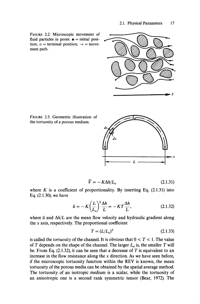
FIGURE 2.3. Geometrie illustration of
the tortuosity of a porous medium.
2.1. Physieal Parameters
17
-r----------------------h--x
~------- L --------~
(2.1.31)
where K is a eoefficient of proportionality. By inserting Eq. (2.1.31) into
Eq. (2.1.30), we have
ü = _K(~)2I1h = _KT l1h
L e L
L'
(2.1.32)
where ü and I1hlL are the mean flow veloeity and hydraulie gradient along
the x axis, respeetively. The proportional eoeffieient
(2.1.33)
is ealled the tortuosity of the ehannel. It is obvious that 0 < T < 1. The value
of T depends on the shape of the ehannel. The larger Le is, the smaller T will
be. From Eq. (2.1.32), it ean be seen that a deerease of T is equivalent to an
inerease in the flow resistanee along the x direetion. As we have seen before,
if the mieroseopie tortuosity funetion within the REV is known, the mean
tortuosity of the porous media ean be obtained by the spatial average method.
The tortuosity of an isotropie medium is a sealar, while the tortuosity of
an anisotropie one is a seeond rank symmetrie tensor (Bear, 1972). The
fluid particJes in pores .• = initial position; 0 = terminal position; -> = movement path.
FIGURE 2.3. Geometrie illustration of
the tortuosity of a porous medium.
2.1. Physieal Parameters
17
-r----------------------h--x
~------- L --------~
(2.1.31)
where K is a eoefficient of proportionality. By inserting Eq. (2.1.31) into
Eq. (2.1.30), we have
ü = _K(~)2I1h = _KT l1h
L e L
L'
(2.1.32)
where ü and I1hlL are the mean flow veloeity and hydraulie gradient along
the x axis, respeetively. The proportional eoeffieient
(2.1.33)
is ealled the tortuosity of the ehannel. It is obvious that 0 < T < 1. The value
of T depends on the shape of the ehannel. The larger Le is, the smaller T will
be. From Eq. (2.1.32), it ean be seen that a deerease of T is equivalent to an
inerease in the flow resistanee along the x direetion. As we have seen before,
if the mieroseopie tortuosity funetion within the REV is known, the mean
tortuosity of the porous media ean be obtained by the spatial average method.
The tortuosity of an isotropie medium is a sealar, while the tortuosity of
an anisotropie one is a seeond rank symmetrie tensor (Bear, 1972). The