

13.3 Solutions
611
(b) Put θ = π to obtain
B =
μ 0 i
4
1
R 1
−
1
R 2
13.31 The total induction is given by adding B s due to the straight conductor which
contributes on both sides of P and B c due to the circular path, both being
directed out of page (Fig. 13.9)
B s =
μ 0 i
2 π R
B c =
μ 0 i
2R
B = B s + B c =
μ 0 i
2π R
(π + 1)
13.32 dB =
μ 0 i
4π
d s × r
r 3
(Biot–Savart law)
(1)
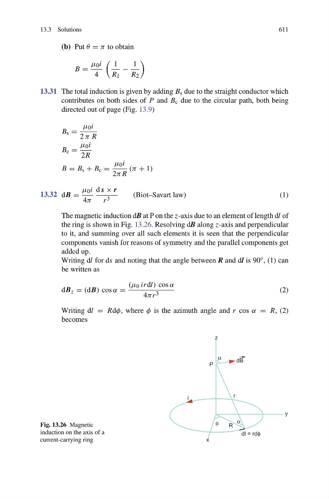
The magnetic induction dB at P on the z-axis due to an element of length dl of
the ring is shown in Fig. 13.26. Resolving dB along z-axis and perpendicular
to it, and summing over all such elements it is seen that the perpendicular
components vanish for reasons of symmetry and the parallel components get
added up.
Writing dl for ds and noting that the angle between R and dl is 90 ◦ , (1) can
be written as
dB z = (dB) cos α =
(μ 0 irdl) cos α
4πr 3
(2)
Writing dl = Rdφ, where φ is the azimuth angle and r cos α = R, (2)
becomes
Fig. 13.26 Magnetic
induction on the axis of a
current-carrying ring