

725
25-3 CAPACITORS I N PARALLE L AN D I N SE R I ES
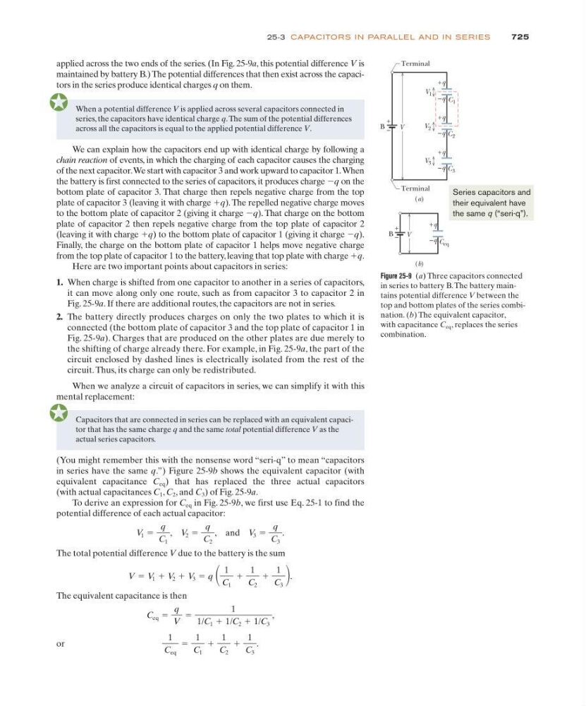
Figure 25-9 (a) Three capacitors connected
in series to battery B. The battery maintains potential difference V between the
top and bottom plates of the series combination. (b) The equivalent capacitor,
with capacitance C eq , replaces the series
combination.
V
(b)
C eq
V
+
–
(a)
B
+q
C 1
C 2
C 3
V 1
V 2
V 3
–
+
B
Terminal
Terminal
–q
+q
–q
–q
+q
–q
+q
Series capacitors and
their equivalent have
the same q (“seri-q”).
applied across the two ends of the series. (In Fig. 25-9a, this potential difference V is
maintained by battery B.) The potential differences that then exist across the capacitors in the series produce identical charges q on them.
Capacitors that are connected in series can be replaced with an equivalent capacitor that has the same charge q and the same total potential difference V as the
actual series capacitors.
(You might remember this with the nonsense word “seri-q” to mean “capacitors
in series have the same q.”) Figure 25-9b shows the equivalent capacitor (with
equivalent capacitance C eq ) that has replaced the three actual capacitors
(with actual capacitances C 1 , C 2 , and C 3 ) of Fig. 25-9a.
To derive an expression for C eq in Fig. 25-9b, we first use Eq. 25-1 to find the
potential difference of each actual capacitor:
The total potential difference V due to the battery is the sum
The equivalent capacitance is then
or
1
C eq
ϭ
1
C 1
ϩ
1
C 2
ϩ
1
C 3
.
C eq ϭ
q
V
ϭ
1
1/C 1 ϩ 1/C 2 ϩ 1/C 3
,
V ϭ V 1 ϩ V 2 ϩ V 3 ϭ q
1
C 1
ϩ
1
C 2
ϩ
1
C 3
.
V 1 ϭ
q
C 1
, V 2 ϭ
q
C 2
, and V 3 ϭ
q
C 3
.
When a potential difference V is applied across several capacitors connected in
series, the capacitors have identical charge q.The sum of the potential differences
across all the capacitors is equal to the applied potential difference V.
We can explain how the capacitors end up with identical charge by following a
chain reaction of events, in which the charging of each capacitor causes the charging
of the next capacitor.We start with capacitor 3 and work upward to capacitor 1.When
the battery is first connected to the series of capacitors, it produces charge Ϫq on the
bottom plate of capacitor 3. That charge then repels negative charge from the top
plate of capacitor 3 (leaving it with charge ϩq). The repelled negative charge moves
to the bottom plate of capacitor 2 (giving it charge Ϫq). That charge on the bottom
plate of capacitor 2 then repels negative charge from the top plate of capacitor 2
(leaving it with charge ϩq) to the bottom plate of capacitor 1 (giving it charge Ϫq).
Finally, the charge on the bottom plate of capacitor 1 helps move negative charge
from the top plate of capacitor 1 to the battery, leaving that top plate with charge ϩq.
Here are two important points about capacitors in series:
1. When charge is shifted from one capacitor to another in a series of capacitors,
it can move along only one route, such as from capacitor 3 to capacitor 2 in
Fig. 25-9a. If there are additional routes, the capacitors are not in series.
2. The battery directly produces charges on only the two plates to which it is
connected (the bottom plate of capacitor 3 and the top plate of capacitor 1 in
Fig. 25-9a). Charges that are produced on the other plates are due merely to
the shifting of charge already there. For example, in Fig. 25-9a, the part of the
circuit enclosed by dashed lines is electrically isolated from the rest of the
circuit. Thus, its charge can only be redistributed.
When we analyze a circuit of capacitors in series, we can simplify it with this
mental replacement: