

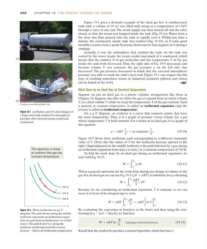
Figure 19-1 gives a dramatic example of the ideal gas law. A stainless-steel
tank with a volume of 18 m
3
was filled with steam at a temperature of 110ЊC
through a valve at one end. The steam supply was then turned off and the valve
closed, so that the steam was trapped inside the tank (Fig. 19-1a). Water from a
fire hose was then poured onto the tank to rapidly cool it. Within less than a
minute, the enormously sturdy tank was crushed (Fig. 19-1b), as if some giant
invisible creature from a grade B science fiction movie had stepped on it during a
rampage.
Actually, it was the atmosphere that crushed the tank. As the tank was
cooled by the water steam, the steam cooled and much of it condensed, which
means that the number N of gas molecules and the temperature T of the gas
inside the tank both decreased. Thus, the right side of Eq. 19-9 decreased, and
because volume V was constant, the gas pressure p on the left side also
decreased. The gas pressure decreased so much that the external atmospheric
pressure was able to crush the tank’s steel wall. Figure 19-1 was staged, but this
type of crushing sometimes occurs in industrial accidents (photos and videos
can be found on the web).
Work Done by an Ideal Gas at Constant Temperature
Suppose we put an ideal gas in a piston – cylinder arrangement like those in
Chapter 18. Suppose also that we allow the gas to expand from an initial volume
V i to a final volume V f while we keep the temperature T of the gas constant. Such
a process, at constant temperature, is called an isothermal expansion (and the
reverse is called an isothermal compression).
On a p-V diagram, an isotherm is a curve that connects points that have
the same temperature. Thus, it is a graph of pressure versus volume for a gas
whose temperature T is held constant. For n moles of an ideal gas, it is a graph of
the equation
(19-10)
Figure 19-2 shows three isotherms, each corresponding to a different (constant)
value of T. (Note that the values of T for the isotherms increase upward to the
right.) Superimposed on the middle isotherm is the path followed by a gas during
an isothermal expansion from state i to state f at a constant temperature of 310 K.
To find the work done by an ideal gas during an isothermal expansion, we
start with Eq. 18-25,
(19-11)
This is a general expression for the work done during any change in volume of any
gas. For an ideal gas, we can use Eq. 19-5 ( pV ϭ nRT) to substitute for p, obtaining
(19-12)
Because we are considering an isothermal expansion, T is constant, so we can
move it in front of the integral sign to write
(19-13)
By evaluating the expression in brackets at the limits and then using the relationship ln a Ϫ ln b ϭ ln(a/b), we find that
(ideal gas, isothermal process).
(19-14)
Recall that the symbol ln specifies a natural logarithm, which has base e.
W ϭ nRT ln
V f
V i
W ϭ nRT ͵
V f
V i
dV
V
ϭ nRT ΄ ln V ΅
V f
V i
.
W ϭ ͵
V f
V i
nRT
V
dV.
W ϭ ͵
V f
V i
p dV.
p ϭ nRT
1
V
ϭ (a constant)
1
V
.
552
CHAPTE R 19 TH E KI N ETIC TH EORY OF GASES
Figure 19-1 (a) Before and (b) after images of
a large steel tank crushed by atmospheric
pressure after internal steam cooled and
condensed.
(a)
(b)
Courtesy www.doctorslime.com
Figure 19-2 Three isotherms on a p-V
diagram. The path shown along the middle
isotherm represents an isothermal expansion of a gas from an initial state i to a final
state f.The path from f to i along the
isotherm would represent the reverse
process — that is, an isothermal compression.
p
V
T = 300 K
T = 310 K
T = 320 K
f
i
The expansion is along
an isotherm (the gas has
constant temperature).
tank with a volume of 18 m
3
was filled with steam at a temperature of 110ЊC
through a valve at one end. The steam supply was then turned off and the valve
closed, so that the steam was trapped inside the tank (Fig. 19-1a). Water from a
fire hose was then poured onto the tank to rapidly cool it. Within less than a
minute, the enormously sturdy tank was crushed (Fig. 19-1b), as if some giant
invisible creature from a grade B science fiction movie had stepped on it during a
rampage.
Actually, it was the atmosphere that crushed the tank. As the tank was
cooled by the water steam, the steam cooled and much of it condensed, which
means that the number N of gas molecules and the temperature T of the gas
inside the tank both decreased. Thus, the right side of Eq. 19-9 decreased, and
because volume V was constant, the gas pressure p on the left side also
decreased. The gas pressure decreased so much that the external atmospheric
pressure was able to crush the tank’s steel wall. Figure 19-1 was staged, but this
type of crushing sometimes occurs in industrial accidents (photos and videos
can be found on the web).
Work Done by an Ideal Gas at Constant Temperature
Suppose we put an ideal gas in a piston – cylinder arrangement like those in
Chapter 18. Suppose also that we allow the gas to expand from an initial volume
V i to a final volume V f while we keep the temperature T of the gas constant. Such
a process, at constant temperature, is called an isothermal expansion (and the
reverse is called an isothermal compression).
On a p-V diagram, an isotherm is a curve that connects points that have
the same temperature. Thus, it is a graph of pressure versus volume for a gas
whose temperature T is held constant. For n moles of an ideal gas, it is a graph of
the equation
(19-10)
Figure 19-2 shows three isotherms, each corresponding to a different (constant)
value of T. (Note that the values of T for the isotherms increase upward to the
right.) Superimposed on the middle isotherm is the path followed by a gas during
an isothermal expansion from state i to state f at a constant temperature of 310 K.
To find the work done by an ideal gas during an isothermal expansion, we
start with Eq. 18-25,
(19-11)
This is a general expression for the work done during any change in volume of any
gas. For an ideal gas, we can use Eq. 19-5 ( pV ϭ nRT) to substitute for p, obtaining
(19-12)
Because we are considering an isothermal expansion, T is constant, so we can
move it in front of the integral sign to write
(19-13)
By evaluating the expression in brackets at the limits and then using the relationship ln a Ϫ ln b ϭ ln(a/b), we find that
(ideal gas, isothermal process).
(19-14)
Recall that the symbol ln specifies a natural logarithm, which has base e.
W ϭ nRT ln
V f
V i
W ϭ nRT ͵
V f
V i
dV
V
ϭ nRT ΄ ln V ΅
V f
V i
.
W ϭ ͵
V f
V i
nRT
V
dV.
W ϭ ͵
V f
V i
p dV.
p ϭ nRT
1
V
ϭ (a constant)
1
V
.
552
CHAPTE R 19 TH E KI N ETIC TH EORY OF GASES
Figure 19-1 (a) Before and (b) after images of
a large steel tank crushed by atmospheric
pressure after internal steam cooled and
condensed.
(a)
(b)
Courtesy www.doctorslime.com
Figure 19-2 Three isotherms on a p-V
diagram. The path shown along the middle
isotherm represents an isothermal expansion of a gas from an initial state i to a final
state f.The path from f to i along the
isotherm would represent the reverse
process — that is, an isothermal compression.
p
V
T = 300 K
T = 310 K
T = 320 K
f
i
The expansion is along
an isotherm (the gas has
constant temperature).