

276
CHAPTE R 10 ROTATION
Sample Problem 10.07 Rotational inertia of a uniform rod, integration
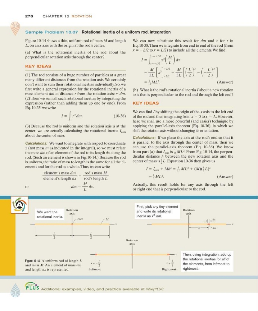
Figure 10-14 shows a thin, uniform rod of mass M and length
L, on an x axis with the origin at the rod’s center.
(a) What is the rotational inertia of the rod about the
perpendicular rotation axis through the center?
KEY IDEAS
(1) The rod consists of a huge number of particles at a great
many different distances from the rotation axis. We certainly
don’t want to sum their rotational inertias individually. So, we
first write a general expression for the rotational inertia of a
mass element dm at distance r from the rotation axis: r
2
dm.
(2) Then we sum all such rotational inertias by integrating the
expression (rather than adding them up one by one). From
Eq. 10-35, we write
(10-38)
(3) Because the rod is uniform and the rotation axis is at the
center, we are actually calculating the rotational inertia I com
about the center of mass.
Calculations: We want to integrate with respect to coordinate
x (not mass m as indicated in the integral), so we must relate
the mass dm of an element of the rod to its length dx along the
rod. (Such an element is shown in Fig. 10-14.) Because the rod
is uniform, the ratio of mass to length is the same for all the elements and for the rod as a whole.Thus, we can write
or
dm ϭ
M
L
dx.
element’s mass dm
element’s length dx
ϭ
rod’s mass M
rod’s length L
I ϭ ͵r
2
dm.
Figure 10-14 A uniform rod of length L
and mass M. An element of mass dm
and length dx is represented.
A
We can now substitute this result for dm and x for r in
Eq. 10-38.Then we integrate from end to end of the rod (from
x ϭ ϪL/2 to x ϭ L/2) to include all the elements.We find
(Answer)
(b) What is the rod’s rotational inertia I about a new rotation
axis that is perpendicular to the rod and through the left end?
KEY IDEAS
We can find I by shifting the origin of the x axis to the left end
of the rod and then integrating from
to
. However,
here we shall use a more powerful (and easier) technique by
applying the parallel-axis theorem (Eq. 10-36), in which we
shift the rotation axis without changing its orientation.
Calculations: If we place the axis at the rod’s end so that it
is parallel to the axis through the center of mass, then we
can use the parallel-axis theorem (Eq. 10-36). We know
from part (a) that I com is
. From Fig. 10-14, the perpendicular distance h between the new rotation axis and the
center of mass is . Equation 10-36 then gives us
(Answer)
Actually, this result holds for any axis through the left
or right end that is perpendicular to the rod.
ϭ
1
3 ML
2
.
I ϭ I com ϩ Mh
2 ϭ
1
12 ML
2 ϩ (M)(
1
2 L)
2
1
2 L
1
12 ML
2
x ϭ L
x ϭ 0
ϭ
1
12 ML
2
.
ϭ
M
3L ΄ x
3
΅
ϪL/2
ϩL/2
ϭ
M
3L ΄
L
2
3
Ϫ Ϫ
L
2
3
΅
I ϭ ͵
xϭϩL/2
xϭϪL/2
x
2
M
L dx
Additional examples, video, and practice available at WileyPLUS
x
Rotation
axis
L
__
2
L
__
2
com
M
We want the
rotational inertia.
x
Rotation
axis
x
dm
dx
First, pick any tiny element
and write its rotational
inertia as x 2 dm.
x
x = −
Rotation
axis
Leftmost
Rightmost
L
__
2
x = L
__
2
Then, using integration, add up
the rotational inertias for all of
the elements, from leftmost to
rightmost.
CHAPTE R 10 ROTATION
Sample Problem 10.07 Rotational inertia of a uniform rod, integration
Figure 10-14 shows a thin, uniform rod of mass M and length
L, on an x axis with the origin at the rod’s center.
(a) What is the rotational inertia of the rod about the
perpendicular rotation axis through the center?
KEY IDEAS
(1) The rod consists of a huge number of particles at a great
many different distances from the rotation axis. We certainly
don’t want to sum their rotational inertias individually. So, we
first write a general expression for the rotational inertia of a
mass element dm at distance r from the rotation axis: r
2
dm.
(2) Then we sum all such rotational inertias by integrating the
expression (rather than adding them up one by one). From
Eq. 10-35, we write
(10-38)
(3) Because the rod is uniform and the rotation axis is at the
center, we are actually calculating the rotational inertia I com
about the center of mass.
Calculations: We want to integrate with respect to coordinate
x (not mass m as indicated in the integral), so we must relate
the mass dm of an element of the rod to its length dx along the
rod. (Such an element is shown in Fig. 10-14.) Because the rod
is uniform, the ratio of mass to length is the same for all the elements and for the rod as a whole.Thus, we can write
or
dm ϭ
M
L
dx.
element’s mass dm
element’s length dx
ϭ
rod’s mass M
rod’s length L
I ϭ ͵r
2
dm.
Figure 10-14 A uniform rod of length L
and mass M. An element of mass dm
and length dx is represented.
A
We can now substitute this result for dm and x for r in
Eq. 10-38.Then we integrate from end to end of the rod (from
x ϭ ϪL/2 to x ϭ L/2) to include all the elements.We find
(Answer)
(b) What is the rod’s rotational inertia I about a new rotation
axis that is perpendicular to the rod and through the left end?
KEY IDEAS
We can find I by shifting the origin of the x axis to the left end
of the rod and then integrating from
to
. However,
here we shall use a more powerful (and easier) technique by
applying the parallel-axis theorem (Eq. 10-36), in which we
shift the rotation axis without changing its orientation.
Calculations: If we place the axis at the rod’s end so that it
is parallel to the axis through the center of mass, then we
can use the parallel-axis theorem (Eq. 10-36). We know
from part (a) that I com is
. From Fig. 10-14, the perpendicular distance h between the new rotation axis and the
center of mass is . Equation 10-36 then gives us
(Answer)
Actually, this result holds for any axis through the left
or right end that is perpendicular to the rod.
ϭ
1
3 ML
2
.
I ϭ I com ϩ Mh
2 ϭ
1
12 ML
2 ϩ (M)(
1
2 L)
2
1
2 L
1
12 ML
2
x ϭ L
x ϭ 0
ϭ
1
12 ML
2
.
ϭ
M
3L ΄ x
3
΅
ϪL/2
ϩL/2
ϭ
M
3L ΄
L
2
3
Ϫ Ϫ
L
2
3
΅
I ϭ ͵
xϭϩL/2
xϭϪL/2
x
2
M
L dx
Additional examples, video, and practice available at WileyPLUS
x
Rotation
axis
L
__
2
L
__
2
com
M
We want the
rotational inertia.
x
Rotation
axis
x
dm
dx
First, pick any tiny element
and write its rotational
inertia as x 2 dm.
x
x = −
Rotation
axis
Leftmost
Rightmost
L
__
2
x = L
__
2
Then, using integration, add up
the rotational inertias for all of
the elements, from leftmost to
rightmost.