

466
C. E. Budde et al.
2 Fault tree analysis
A fault tree ‘’ is a directed acyclic graph that models how component failures
propagate and eventually cause the full system to fail. We consider repairable
fault trees (RFTs), where failures and repairs are governed by arbitrary probability distributions.
BE 1
BE n
(a) AND
BE 1
BE n
(b) OR
k/n
BE 1
BE n
(c) VOT k
BE 1
BE 2
(d) PAND
S 1
S m
P
(e) SPARE
T
BE 1
BE n
(f) FDEP
BE 1
BE n
(g) RBOX
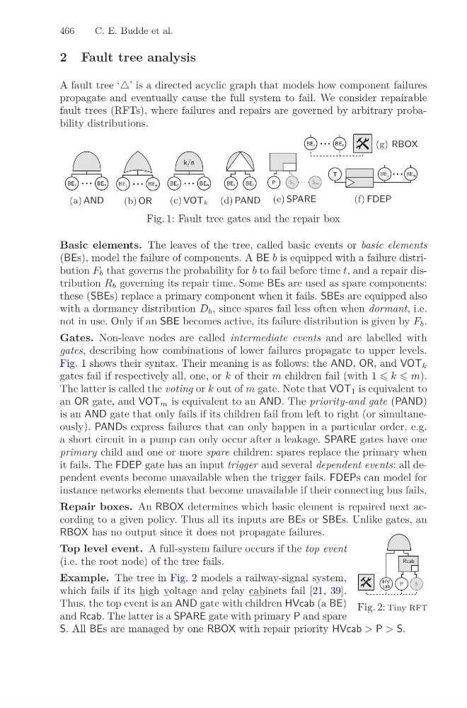
Fig. 1: Fault tree gates and the repair box
Basic elements. The leaves of the tree, called basic events or basic elements
(BEs), model the failure of components. A BE b is equipped with a failure distribution F b that governs the probability for b to fail before time t, and a repair distribution R b governing its repair time. Some BEs are used as spare components:
these (SBEs) replace a primary component when it fails. SBEs are equipped also
with a dormancy distribution D b , since spares fail less often when dormant, i.e.
not in use. Only if an SBE becomes active, its failure distribution is given by F b .
Gates. Non-leave nodes are called intermediate events and are labelled with
gates, describing how combinations of lower failures propagate to upper levels.
Fig. 1 shows their syntax. Their meaning is as follows: the AND, OR, and VOT k
gates fail if respectively all, one, or k of their m children fail (with 1 k m).
The latter is called the voting or k out of m gate. Note that VOT 1 is equivalent to
an OR gate, and VOT m is equivalent to an AND. The priority-and gate (PAND)
is an AND gate that only fails if its children fail from left to right (or simultaneously). PANDs express failures that can only happen in a particular order, e.g.
a short circuit in a pump can only occur after a leakage. SPARE gates have one
primary child and one or more spare children: spares replace the primary when
it fails. The FDEP gate has an input trigger and several dependent events: all dependent events become unavailable when the trigger fails. FDEPs can model for
instance networks elements that become unavailable if their connecting bus fails.
Repair boxes. An RBOX determines which basic element is repaired next according to a given policy. Thus all its inputs are BEs or SBEs. Unlike gates, an
RBOX has no output since it does not propagate failures.
HV
cab
P
S
Rcab
Fig. 2: Tiny rft
Top level event. A full-system failure occurs if the top event
(i.e. the root node) of the tree fails.
Example. The tree in Fig. 2 models a railway-signal system,
which fails if its high voltage and relay cabinets fail [21, 39].
Thus, the top event is an AND gate with children HVcab (a BE)
and Rcab. The latter is a SPARE gate with primary P and spare
S. All BEs are managed by one RBOX with repair priority HVcab > P > S.
C. E. Budde et al.
2 Fault tree analysis
A fault tree ‘’ is a directed acyclic graph that models how component failures
propagate and eventually cause the full system to fail. We consider repairable
fault trees (RFTs), where failures and repairs are governed by arbitrary probability distributions.
BE 1
BE n
(a) AND
BE 1
BE n
(b) OR
k/n
BE 1
BE n
(c) VOT k
BE 1
BE 2
(d) PAND
S 1
S m
P
(e) SPARE
T
BE 1
BE n
(f) FDEP
BE 1
BE n
(g) RBOX
Fig. 1: Fault tree gates and the repair box
Basic elements. The leaves of the tree, called basic events or basic elements
(BEs), model the failure of components. A BE b is equipped with a failure distribution F b that governs the probability for b to fail before time t, and a repair distribution R b governing its repair time. Some BEs are used as spare components:
these (SBEs) replace a primary component when it fails. SBEs are equipped also
with a dormancy distribution D b , since spares fail less often when dormant, i.e.
not in use. Only if an SBE becomes active, its failure distribution is given by F b .
Gates. Non-leave nodes are called intermediate events and are labelled with
gates, describing how combinations of lower failures propagate to upper levels.
Fig. 1 shows their syntax. Their meaning is as follows: the AND, OR, and VOT k
gates fail if respectively all, one, or k of their m children fail (with 1 k m).
The latter is called the voting or k out of m gate. Note that VOT 1 is equivalent to
an OR gate, and VOT m is equivalent to an AND. The priority-and gate (PAND)
is an AND gate that only fails if its children fail from left to right (or simultaneously). PANDs express failures that can only happen in a particular order, e.g.
a short circuit in a pump can only occur after a leakage. SPARE gates have one
primary child and one or more spare children: spares replace the primary when
it fails. The FDEP gate has an input trigger and several dependent events: all dependent events become unavailable when the trigger fails. FDEPs can model for
instance networks elements that become unavailable if their connecting bus fails.
Repair boxes. An RBOX determines which basic element is repaired next according to a given policy. Thus all its inputs are BEs or SBEs. Unlike gates, an
RBOX has no output since it does not propagate failures.
HV
cab
P
S
Rcab
Fig. 2: Tiny rft
Top level event. A full-system failure occurs if the top event
(i.e. the root node) of the tree fails.
Example. The tree in Fig. 2 models a railway-signal system,
which fails if its high voltage and relay cabinets fail [21, 39].
Thus, the top event is an AND gate with children HVcab (a BE)
and Rcab. The latter is a SPARE gate with primary P and spare
S. All BEs are managed by one RBOX with repair priority HVcab > P > S.