

Multi-Agent Safety Verification using Symmetry Transformations
187
6.2 Experimental results
We ran experiments using our tool CacheReach on two models: a 3-dimensional linear
dynamical system example and the nonlinear aircraft model described in Example 1. The
linear model is of the form ˙
x = A(x− p[3 : 5]), where A = [[−3, 1, 0], [0, −2, 1], [0, 0, −1]],
x ∈ R 3 , and p ∈ R 6 . We considered scenarios with single, two, and three agents for each
model following different sequences of waypoints. The sequences of waypoints for the
linear model are translations and rotations of a digital-S shaped path. For the aircraft
model, the paths are random crossing paths going north-east. In every scenario, all the
agents have the same model. In the aircraft scenarios, the agent would switch to the next
waypoint once its x, y position is within 0.5 units from the current waypoint in each
dimension. The initial set of the aircraft was of size 1 in the position components, 0.1 in
the speed, and 0.01 in the heading angle. We used Flow* [8] and DryVR [18] to compute
reachtubes from scratch for the linear example. We only used DryVR for the aircraft
model since our C++ Flow* wrapper does not handle a model having arctan 2 in the
dynamics. We ran all scenarios in CacheReach with and without using tubecache. The
symmetry used for the aircraft was the one we showed in Example 3. For the linear model,
the symmetry transformation γ p that was used to map the state to the virtual system
was a coordinate transformation where the new origin is at the next waypoint p[3 : 5]
and rotating the xy-plane by the angle between the previous and the next waypoints
p[0 : 2] and p[3 : 5] projected to the plane. We compared the computation time with and
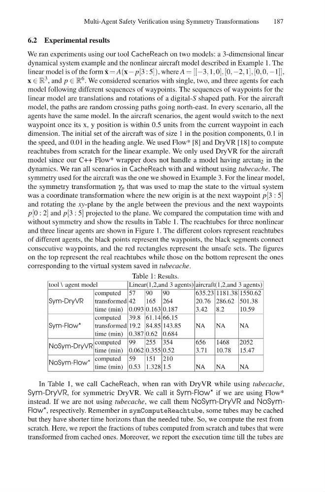
without symmetry and show the results in Table 1. The reachtubes for three nonlinear
and three linear agents are shown in Figure 1. The different colors represent reachtubes
of different agents, the black points represent the waypoints, the black segments connect
consecutive waypoints, and the red rectangles represent the unsafe sets. The figures
on the top represent the real reachtubes while those on the bottom represent the ones
corresponding to the virtual system saved in tubecache.
Table 1: Results.
tool \ agent model
Linear(1,2,and 3 agents) aircraft(1,2,and 3 agents)
Sym-DryVR
computed 57
90
90
635.23 1181.38 1550.62
transformed 42
165 264
20.76 286.62 501.38
time (min) 0.093 0.163 0.187
3.42 8.2
10.59
Sym-Flow*
computed 39.8 61.14 66.15
transformed 19.2 84.85 143.85
NA
NA
NA
time (min) 0.387 0.62 0.684
NoSym-DryVR
computed 99
255 354
656
1468
2052
time (min) 0.062 0.355 0.52
3.71 10.78 15.47
NoSym-Flow*
computed 59
151 210
time (min) 0.53 1.328 1.5
NA
NA
NA
In Table 1, we call CacheReach, when ran with DryVR while using tubecache,
Sym-DryVR, for symmetric DryVR. We call it Sym-Flow* if we are using Flow*
instead. If we are not using tubecache, we call them NoSym-DryVR and NoSymFlow*, respectively. Remember in symComputeReachtube, some tubes may be cached
but they have shorter time horizons than the needed tube. So, we compute the rest from
scratch. Here, we report the fractions of tubes computed from scratch and tubes that were
transformed from cached ones. Moreover, we report the execution time till the tubes are
187
6.2 Experimental results
We ran experiments using our tool CacheReach on two models: a 3-dimensional linear
dynamical system example and the nonlinear aircraft model described in Example 1. The
linear model is of the form ˙
x = A(x− p[3 : 5]), where A = [[−3, 1, 0], [0, −2, 1], [0, 0, −1]],
x ∈ R 3 , and p ∈ R 6 . We considered scenarios with single, two, and three agents for each
model following different sequences of waypoints. The sequences of waypoints for the
linear model are translations and rotations of a digital-S shaped path. For the aircraft
model, the paths are random crossing paths going north-east. In every scenario, all the
agents have the same model. In the aircraft scenarios, the agent would switch to the next
waypoint once its x, y position is within 0.5 units from the current waypoint in each
dimension. The initial set of the aircraft was of size 1 in the position components, 0.1 in
the speed, and 0.01 in the heading angle. We used Flow* [8] and DryVR [18] to compute
reachtubes from scratch for the linear example. We only used DryVR for the aircraft
model since our C++ Flow* wrapper does not handle a model having arctan 2 in the
dynamics. We ran all scenarios in CacheReach with and without using tubecache. The
symmetry used for the aircraft was the one we showed in Example 3. For the linear model,
the symmetry transformation γ p that was used to map the state to the virtual system
was a coordinate transformation where the new origin is at the next waypoint p[3 : 5]
and rotating the xy-plane by the angle between the previous and the next waypoints
p[0 : 2] and p[3 : 5] projected to the plane. We compared the computation time with and
without symmetry and show the results in Table 1. The reachtubes for three nonlinear
and three linear agents are shown in Figure 1. The different colors represent reachtubes
of different agents, the black points represent the waypoints, the black segments connect
consecutive waypoints, and the red rectangles represent the unsafe sets. The figures
on the top represent the real reachtubes while those on the bottom represent the ones
corresponding to the virtual system saved in tubecache.
Table 1: Results.
tool \ agent model
Linear(1,2,and 3 agents) aircraft(1,2,and 3 agents)
Sym-DryVR
computed 57
90
90
635.23 1181.38 1550.62
transformed 42
165 264
20.76 286.62 501.38
time (min) 0.093 0.163 0.187
3.42 8.2
10.59
Sym-Flow*
computed 39.8 61.14 66.15
transformed 19.2 84.85 143.85
NA
NA
NA
time (min) 0.387 0.62 0.684
NoSym-DryVR
computed 99
255 354
656
1468
2052
time (min) 0.062 0.355 0.52
3.71 10.78 15.47
NoSym-Flow*
computed 59
151 210
time (min) 0.53 1.328 1.5
NA
NA
NA
In Table 1, we call CacheReach, when ran with DryVR while using tubecache,
Sym-DryVR, for symmetric DryVR. We call it Sym-Flow* if we are using Flow*
instead. If we are not using tubecache, we call them NoSym-DryVR and NoSymFlow*, respectively. Remember in symComputeReachtube, some tubes may be cached
but they have shorter time horizons than the needed tube. So, we compute the rest from
scratch. Here, we report the fractions of tubes computed from scratch and tubes that were
transformed from cached ones. Moreover, we report the execution time till the tubes are