

7.3 Flow-Corrective Insert Optimization
469
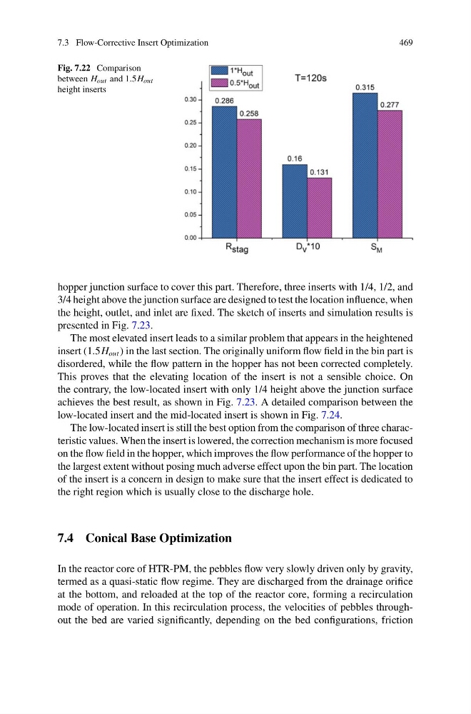
Fig. 7.22 Comparison
between H out and 1.5H out
height inserts
hopper junction surface to cover this part. Therefore, three inserts with 1/4, 1/2, and
3/4 height above the junction surface are designed to test the location influence, when
the height, outlet, and inlet are fixed. The sketch of inserts and simulation results is
presented in Fig. 7.23.
The most elevated insert leads to a similar problem that appears in the heightened
insert (1.5H out ) in the last section. The originally uniform flow field in the bin part is
disordered, while the flow pattern in the hopper has not been corrected completely.
This proves that the elevating location of the insert is not a sensible choice. On
the contrary, the low-located insert with only 1/4 height above the junction surface
achieves the best result, as shown in Fig. 7.23. A detailed comparison between the
low-located insert and the mid-located insert is shown in Fig. 7.24.
The low-located insert is still the best option from the comparison of three characteristic values. When the insert is lowered, the correction mechanism is more focused
on the flow field in the hopper, which improves the flow performance of the hopper to
the largest extent without posing much adverse effect upon the bin part. The location
of the insert is a concern in design to make sure that the insert effect is dedicated to
the right region which is usually close to the discharge hole.
7.4 Conical Base Optimization
In the reactor core of HTR-PM, the pebbles flow very slowly driven only by gravity,
termed as a quasi-static flow regime. They are discharged from the drainage orifice
at the bottom, and reloaded at the top of the reactor core, forming a recirculation
mode of operation. In this recirculation process, the velocities of pebbles throughout the bed are varied significantly, depending on the bed configurations, friction
469
Fig. 7.22 Comparison
between H out and 1.5H out
height inserts
hopper junction surface to cover this part. Therefore, three inserts with 1/4, 1/2, and
3/4 height above the junction surface are designed to test the location influence, when
the height, outlet, and inlet are fixed. The sketch of inserts and simulation results is
presented in Fig. 7.23.
The most elevated insert leads to a similar problem that appears in the heightened
insert (1.5H out ) in the last section. The originally uniform flow field in the bin part is
disordered, while the flow pattern in the hopper has not been corrected completely.
This proves that the elevating location of the insert is not a sensible choice. On
the contrary, the low-located insert with only 1/4 height above the junction surface
achieves the best result, as shown in Fig. 7.23. A detailed comparison between the
low-located insert and the mid-located insert is shown in Fig. 7.24.
The low-located insert is still the best option from the comparison of three characteristic values. When the insert is lowered, the correction mechanism is more focused
on the flow field in the hopper, which improves the flow performance of the hopper to
the largest extent without posing much adverse effect upon the bin part. The location
of the insert is a concern in design to make sure that the insert effect is dedicated to
the right region which is usually close to the discharge hole.
7.4 Conical Base Optimization
In the reactor core of HTR-PM, the pebbles flow very slowly driven only by gravity,
termed as a quasi-static flow regime. They are discharged from the drainage orifice
at the bottom, and reloaded at the top of the reactor core, forming a recirculation
mode of operation. In this recirculation process, the velocities of pebbles throughout the bed are varied significantly, depending on the bed configurations, friction