

122
3 Experiments in Pebble Bed Heat Transfer
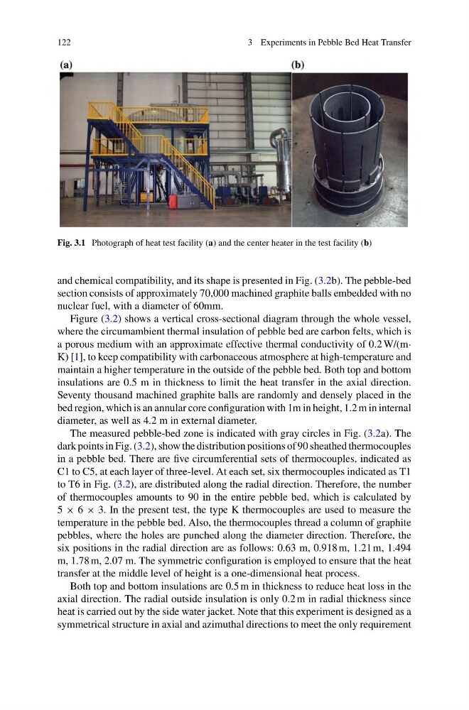
Fig. 3.1 Photograph of heat test facility (a) and the center heater in the test facility (b)
and chemical compatibility, and its shape is presented in Fig. (3.2b). The pebble-bed
section consists of approximately 70,000 machined graphite balls embedded with no
nuclear fuel, with a diameter of 60mm.
Figure (3.2) shows a vertical cross-sectional diagram through the whole vessel,
where the circumambient thermal insulation of pebble bed are carbon felts, which is
a porous medium with an approximate effective thermal conductivity of 0.2 W/(m·
K) [1], to keep compatibility with carbonaceous atmosphere at high-temperature and
maintain a higher temperature in the outside of the pebble bed. Both top and bottom
insulations are 0.5 m in thickness to limit the heat transfer in the axial direction.
Seventy thousand machined graphite balls are randomly and densely placed in the
bed region, which is an annular core configuration with 1m in height, 1.2 m in internal
diameter, as well as 4.2 m in external diameter.
The measured pebble-bed zone is indicated with gray circles in Fig. (3.2a). The
dark points in Fig. (3.2), show the distribution positions of 90 sheathed thermocouples
in a pebble bed. There are five circumferential sets of thermocouples, indicated as
C1 to C5, at each layer of three-level. At each set, six thermocouples indicated as T1
to T6 in Fig. (3.2), are distributed along the radial direction. Therefore, the number
of thermocouples amounts to 90 in the entire pebble bed, which is calculated by
5 × 6 × 3. In the present test, the type K thermocouples are used to measure the
temperature in the pebble bed. Also, the thermocouples thread a column of graphite
pebbles, where the holes are punched along the diameter direction. Therefore, the
six positions in the radial direction are as follows: 0.63 m, 0.918 m, 1.21 m, 1.494
m, 1.78 m, 2.07 m. The symmetric configuration is employed to ensure that the heat
transfer at the middle level of height is a one-dimensional heat process.
Both top and bottom insulations are 0.5 m in thickness to reduce heat loss in the
axial direction. The radial outside insulation is only 0.2 m in radial thickness since
heat is carried out by the side water jacket. Note that this experiment is designed as a
symmetrical structure in axial and azimuthal directions to meet the only requirement
3 Experiments in Pebble Bed Heat Transfer
Fig. 3.1 Photograph of heat test facility (a) and the center heater in the test facility (b)
and chemical compatibility, and its shape is presented in Fig. (3.2b). The pebble-bed
section consists of approximately 70,000 machined graphite balls embedded with no
nuclear fuel, with a diameter of 60mm.
Figure (3.2) shows a vertical cross-sectional diagram through the whole vessel,
where the circumambient thermal insulation of pebble bed are carbon felts, which is
a porous medium with an approximate effective thermal conductivity of 0.2 W/(m·
K) [1], to keep compatibility with carbonaceous atmosphere at high-temperature and
maintain a higher temperature in the outside of the pebble bed. Both top and bottom
insulations are 0.5 m in thickness to limit the heat transfer in the axial direction.
Seventy thousand machined graphite balls are randomly and densely placed in the
bed region, which is an annular core configuration with 1m in height, 1.2 m in internal
diameter, as well as 4.2 m in external diameter.
The measured pebble-bed zone is indicated with gray circles in Fig. (3.2a). The
dark points in Fig. (3.2), show the distribution positions of 90 sheathed thermocouples
in a pebble bed. There are five circumferential sets of thermocouples, indicated as
C1 to C5, at each layer of three-level. At each set, six thermocouples indicated as T1
to T6 in Fig. (3.2), are distributed along the radial direction. Therefore, the number
of thermocouples amounts to 90 in the entire pebble bed, which is calculated by
5 × 6 × 3. In the present test, the type K thermocouples are used to measure the
temperature in the pebble bed. Also, the thermocouples thread a column of graphite
pebbles, where the holes are punched along the diameter direction. Therefore, the
six positions in the radial direction are as follows: 0.63 m, 0.918 m, 1.21 m, 1.494
m, 1.78 m, 2.07 m. The symmetric configuration is employed to ensure that the heat
transfer at the middle level of height is a one-dimensional heat process.
Both top and bottom insulations are 0.5 m in thickness to reduce heat loss in the
axial direction. The radial outside insulation is only 0.2 m in radial thickness since
heat is carried out by the side water jacket. Note that this experiment is designed as a
symmetrical structure in axial and azimuthal directions to meet the only requirement