

A.3 Fresnel Factors for Three-Layer Model
39
0
30
60
90
0.2
0.4
0.6
0.8
1.0
0.0
0
30
60
90
0.2
0.4
0.6
0.8
1.0
0.0
30
60
90
2
4
6
8
0
0
30
60
90
1
2
3
4
0
0
(a) |r |
P
(b) |t |
P
(c) |r |
S
(d) |t |
S
2
2
2
2
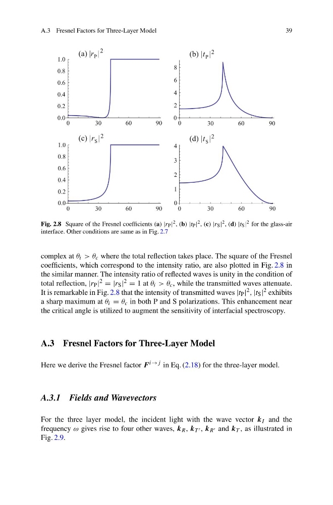
Fig. 2.8 Square of the Fresnel coefficients (a) |r P | 2 , (b) |t P | 2 , (c) |r S | 2 , (d) |t S | 2 for the glass-air
interface. Other conditions are same as in Fig. 2.7
complex at θ i > θ c where the total reflection takes place. The square of the Fresnel
coefficients, which correspond to the intensity ratio, are also plotted in Fig. 2.8 in
the similar manner. The intensity ratio of reflected waves is unity in the condition of
total reflection, |r P | 2 = |r S | 2 = 1 at θ i > θ c , while the transmitted waves attenuate.
It is remarkable in Fig. 2.8 that the intensity of transmitted waves |t P | 2 , |t S | 2 exhibits
a sharp maximum at θ i = θ c in both P and S polarizations. This enhancement near
the critical angle is utilized to augment the sensitivity of interfacial spectroscopy.
A.3 Fresnel Factors for Three-Layer Model
Here we derive the Fresnel factor F i→j in Eq. (2.18) for the three-layer model.
A.3.1 Fields and Wavevectors
For the three layer model, the incident light with the wave vector k I and the
frequency ω gives rise to four other waves, k R , k T , k R and k T , as illustrated in
Fig. 2.9.
39
0
30
60
90
0.2
0.4
0.6
0.8
1.0
0.0
0
30
60
90
0.2
0.4
0.6
0.8
1.0
0.0
30
60
90
2
4
6
8
0
0
30
60
90
1
2
3
4
0
0
(a) |r |
P
(b) |t |
P
(c) |r |
S
(d) |t |
S
2
2
2
2
Fig. 2.8 Square of the Fresnel coefficients (a) |r P | 2 , (b) |t P | 2 , (c) |r S | 2 , (d) |t S | 2 for the glass-air
interface. Other conditions are same as in Fig. 2.7
complex at θ i > θ c where the total reflection takes place. The square of the Fresnel
coefficients, which correspond to the intensity ratio, are also plotted in Fig. 2.8 in
the similar manner. The intensity ratio of reflected waves is unity in the condition of
total reflection, |r P | 2 = |r S | 2 = 1 at θ i > θ c , while the transmitted waves attenuate.
It is remarkable in Fig. 2.8 that the intensity of transmitted waves |t P | 2 , |t S | 2 exhibits
a sharp maximum at θ i = θ c in both P and S polarizations. This enhancement near
the critical angle is utilized to augment the sensitivity of interfacial spectroscopy.
A.3 Fresnel Factors for Three-Layer Model
Here we derive the Fresnel factor F i→j in Eq. (2.18) for the three-layer model.
A.3.1 Fields and Wavevectors
For the three layer model, the incident light with the wave vector k I and the
frequency ω gives rise to four other waves, k R , k T , k R and k T , as illustrated in
Fig. 2.9.