

13 Spinoptics in Plasmonics
479
2μm
1 μm
1
=
1
−
=
(a)
2 μm
(c)
(e)
(b)
(d)
(f)
σ
σ
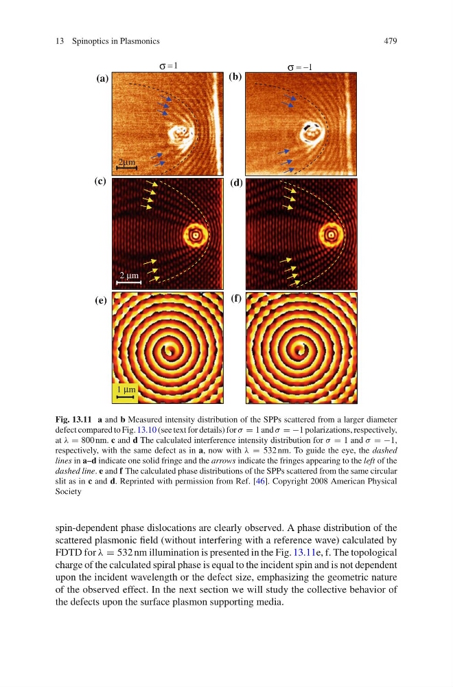
Fig. 13.11 a and b Measured intensity distribution of the SPPs scattered from a larger diameter
defect compared to Fig. 13.10 (see text for details) for λ = 1 and λ = −1 polarizations, respectively,
at ε = 800 nm. c and d The calculated interference intensity distribution for λ = 1 and λ = −1,
respectively, with the same defect as in a, now with ε = 532 nm. To guide the eye, the dashed
lines in a–d indicate one solid fringe and the arrows indicate the fringes appearing to the left of the
dashed line. e and f The calculated phase distributions of the SPPs scattered from the same circular
slit as in c and d. Reprinted with permission from Ref. [46]. Copyright 2008 American Physical
Society
spin-dependent phase dislocations are clearly observed. A phase distribution of the
scattered plasmonic field (without interfering with a reference wave) calculated by
FDTD for ε = 532 nm illumination is presented in the Fig. 13.11e, f. The topological
charge of the calculated spiral phase is equal to the incident spin and is not dependent
upon the incident wavelength or the defect size, emphasizing the geometric nature
of the observed effect. In the next section we will study the collective behavior of
the defects upon the surface plasmon supporting media.
479
2μm
1 μm
1
=
1
−
=
(a)
2 μm
(c)
(e)
(b)
(d)
(f)
σ
σ
Fig. 13.11 a and b Measured intensity distribution of the SPPs scattered from a larger diameter
defect compared to Fig. 13.10 (see text for details) for λ = 1 and λ = −1 polarizations, respectively,
at ε = 800 nm. c and d The calculated interference intensity distribution for λ = 1 and λ = −1,
respectively, with the same defect as in a, now with ε = 532 nm. To guide the eye, the dashed
lines in a–d indicate one solid fringe and the arrows indicate the fringes appearing to the left of the
dashed line. e and f The calculated phase distributions of the SPPs scattered from the same circular
slit as in c and d. Reprinted with permission from Ref. [46]. Copyright 2008 American Physical
Society
spin-dependent phase dislocations are clearly observed. A phase distribution of the
scattered plasmonic field (without interfering with a reference wave) calculated by
FDTD for ε = 532 nm illumination is presented in the Fig. 13.11e, f. The topological
charge of the calculated spiral phase is equal to the incident spin and is not dependent
upon the incident wavelength or the defect size, emphasizing the geometric nature
of the observed effect. In the next section we will study the collective behavior of
the defects upon the surface plasmon supporting media.