

476
E. Hasman and V. Kleiner
NSOM
Au
SiO 2
1
±
=
σ
Laser
QWP
2 μm
(a)
r
ξ
1 μm
(b)
(c)
detector
ϕ
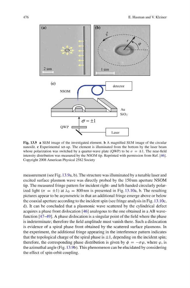
Fig. 13.9 a SEM image of the investigated element. b A magnified SEM image of the circular
nanoslit. c Experimental set-up. The element is illuminated from the bottom by the laser beam
whose polarization was switched by a quarter-wave plate (QWP) to be λ = ±1. The near-field
intensity distribution was measured by the NSOM tip. Reprinted with permission from Ref. [46].
Copyright 2008 American Physical 2582 Society
measurement (see Fig. 13.9a, b). The structure was illuminated by a tunable laser and
excited surface plasmon wave was directly probed by the 150 nm aperture NSOM
tip. The measured fringe pattern for incident right- and left-handed circularly polarized light (λ = ±1) at ε 0 = 800 nm is presented in Fig. 13.10a, b. The resulting
pictures appear to be asymmetric in that an additional fringe emerge above or below
the coaxial aperture according to the incident spin (see fringe analysis in Fig. 13.10c,
d). It can be concluded that a plasmonic wave scattered by the cylindrical defect
acquires a phase front dislocation [46] analogous to the one obtained in a AB wavefunction [47–49]. A phase dislocation is a singular point of the field where the phase
is indeterminate; therefore the field amplitude must vanish there. Such a dislocation
is evidence of a spiral phase front obtained by the scattered surface plasmons. In
the experiment, the additional fringe appearing in the interference pattern indicates
that the topological charge of the spiral phase is ±1, depending on the incident spin;
therefore, the corresponding phase distribution is given by γ = −λ π, where π, is
the azimuthal angle (Fig. 13.9b). This phenomenon can be elucidated by considering
the effect of spin-orbit coupling.
E. Hasman and V. Kleiner
NSOM
Au
SiO 2
1
±
=
σ
Laser
QWP
2 μm
(a)
r
ξ
1 μm
(b)
(c)
detector
ϕ
Fig. 13.9 a SEM image of the investigated element. b A magnified SEM image of the circular
nanoslit. c Experimental set-up. The element is illuminated from the bottom by the laser beam
whose polarization was switched by a quarter-wave plate (QWP) to be λ = ±1. The near-field
intensity distribution was measured by the NSOM tip. Reprinted with permission from Ref. [46].
Copyright 2008 American Physical 2582 Society
measurement (see Fig. 13.9a, b). The structure was illuminated by a tunable laser and
excited surface plasmon wave was directly probed by the 150 nm aperture NSOM
tip. The measured fringe pattern for incident right- and left-handed circularly polarized light (λ = ±1) at ε 0 = 800 nm is presented in Fig. 13.10a, b. The resulting
pictures appear to be asymmetric in that an additional fringe emerge above or below
the coaxial aperture according to the incident spin (see fringe analysis in Fig. 13.10c,
d). It can be concluded that a plasmonic wave scattered by the cylindrical defect
acquires a phase front dislocation [46] analogous to the one obtained in a AB wavefunction [47–49]. A phase dislocation is a singular point of the field where the phase
is indeterminate; therefore the field amplitude must vanish there. Such a dislocation
is evidence of a spiral phase front obtained by the scattered surface plasmons. In
the experiment, the additional fringe appearing in the interference pattern indicates
that the topological charge of the spiral phase is ±1, depending on the incident spin;
therefore, the corresponding phase distribution is given by γ = −λ π, where π, is
the azimuthal angle (Fig. 13.9b). This phenomenon can be elucidated by considering
the effect of spin-orbit coupling.