

11 Plasmonic Functionalities Based on Detuned Electrical Dipoles
423
16
12
8
4
0
|E/E |
0
(e)
(f)
(g)
λ =1370nm
λ=1520nm
λ=1640nm
(c)
(d)
(b)
(a)
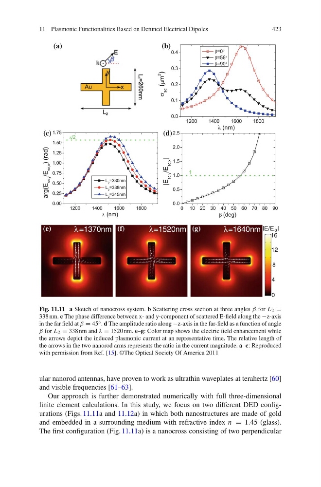
Fig. 11.11 a Sketch of nanocross system. b Scattering cross section at three angles Ω for L 2 =
338 nm. c The phase difference between x- and y-component of scattered E-field along the −z-axis
in the far field at Ω = 45 ◦ . d The amplitude ratio along −z-axis in the far-field as a function of angle
Ω for L 2 = 338 nm and ϕ = 1520 nm. e–g: Color map shows the electric field enhancement while
the arrows depict the induced plasmonic current at an representative time. The relative length of
the arrows in the two nanorod arms represents the ratio in the current magnitude. a–c: Reproduced
with permission from Ref. [15]. ©The Optical Society Of America 2011
ular nanorod antennas, have proven to work as ultrathin waveplates at terahertz [60]
and visible frequencies [61–63].
Our approach is further demonstrated numerically with full three-dimensional
finite element calculations. In this study, we focus on two different DED configurations (Figs. 11.11a and 11.12a) in which both nanostructures are made of gold
and embedded in a surrounding medium with refractive index n = 1.45 (glass).
The first configuration (Fig. 11.11a) is a nanocross consisting of two perpendicular
423
16
12
8
4
0
|E/E |
0
(e)
(f)
(g)
λ =1370nm
λ=1520nm
λ=1640nm
(c)
(d)
(b)
(a)
Fig. 11.11 a Sketch of nanocross system. b Scattering cross section at three angles Ω for L 2 =
338 nm. c The phase difference between x- and y-component of scattered E-field along the −z-axis
in the far field at Ω = 45 ◦ . d The amplitude ratio along −z-axis in the far-field as a function of angle
Ω for L 2 = 338 nm and ϕ = 1520 nm. e–g: Color map shows the electric field enhancement while
the arrows depict the induced plasmonic current at an representative time. The relative length of
the arrows in the two nanorod arms represents the ratio in the current magnitude. a–c: Reproduced
with permission from Ref. [15]. ©The Optical Society Of America 2011
ular nanorod antennas, have proven to work as ultrathin waveplates at terahertz [60]
and visible frequencies [61–63].
Our approach is further demonstrated numerically with full three-dimensional
finite element calculations. In this study, we focus on two different DED configurations (Figs. 11.11a and 11.12a) in which both nanostructures are made of gold
and embedded in a surrounding medium with refractive index n = 1.45 (glass).
The first configuration (Fig. 11.11a) is a nanocross consisting of two perpendicular