

3 Theoretical Models of Light Scattering and Absorption
57
Thus, in this example, the fraction of light absorbed (0.3%) is determined by the
ability of the layer to absorb light and has not been influenced by scatter. Consequently, if one calculated an absorption coefficient from this layer, one could say
that the resulting coefficient was a true measurement of the absorbing power of the
material for light at that wavelength. This, then, is a more fundamental property of
the material than an absorption coefficient obtained from a macroscopic sample, and
therefore expected to be more broadly applicable to other samples involving the same
material.
It is generally not realistic to fashion an extremely thin sample like the one pictured
in Fig. 3.11. However, Benford’s equations (Sect. 3.8) give us a way to calculate A,
R, and T for a sample of any thickness, given A, R, and T for a sample of any
other thickness. Thus, we can mathematically model the behavior of a hypothetical
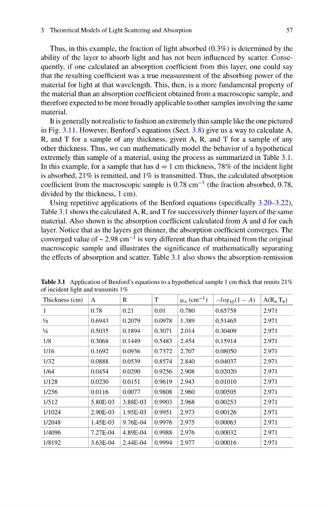
extremely thin sample of a material, using the process as summarized in Table 3.1.
In this example, for a sample that has d = 1 cm thickness, 78% of the incident light
is absorbed, 21% is remitted, and 1% is transmitted. Thus, the calculated absorption
coefficient from the macroscopic sample is 0.78 cm
−1 (the fraction absorbed, 0.78,
divided by the thickness, 1 cm).
Using repetitive applications of the Benford equations (specifically 3.20–3.22),
Table 3.1 shows the calculated A, R, and T for successively thinner layers of the same
material. Also shown is the absorption coefficient calculated from A and d for each
layer. Notice that as the layers get thinner, the absorption coefficient converges. The
converged value of ~ 2.98 cm
−1 is very different than that obtained from the original
macroscopic sample and illustrates the significance of mathematically separating
the effects of absorption and scatter. Table 3.1 also shows the absorption-remission
Table 3.1 Application of Benford’s equations to a hypothetical sample 1 cm thick that remits 21%
of incident light and transmits 1%
Thickness (cm) A
R
T
μ a (cm −1 ) −log 10 (1 − A) A(R n, T n )
1
0.78
0.21
0.01
0.780
0.65758
2.971
½
0.6943
0.2079
0.0978 1.389
0.51465
2.971
¼
0.5035
0.1894
0.3071 2.014
0.30409
2.971
1/8
0.3068
0.1449
0.5483 2.454
0.15914
2.971
1/16
0.1692
0.0936
0.7372 2.707
0.08050
2.971
1/32
0.0888
0.0539
0.8574 2.840
0.04037
2.971
1/64
0.0454
0.0290
0.9256 2.908
0.02020
2.971
1/128
0.0230
0.0151
0.9619 2.943
0.01010
2.971
1/256
0.0116
0.0077
0.9808 2.960
0.00505
2.971
1/512
5.80E-03 3.88E-03 0.9903 2.968
0.00253
2.971
1/1024
2.90E-03 1.95E-03 0.9951 2.973
0.00126
2.971
1/2048
1.45E-03 9.76E-04 0.9976 2.975
0.00063
2.971
1/4096
7.27E-04 4.89E-04 0.9988 2.976
0.00032
2.971
1/8192
3.63E-04 2.44E-04 0.9994 2.977
0.00016
2.971
57
Thus, in this example, the fraction of light absorbed (0.3%) is determined by the
ability of the layer to absorb light and has not been influenced by scatter. Consequently, if one calculated an absorption coefficient from this layer, one could say
that the resulting coefficient was a true measurement of the absorbing power of the
material for light at that wavelength. This, then, is a more fundamental property of
the material than an absorption coefficient obtained from a macroscopic sample, and
therefore expected to be more broadly applicable to other samples involving the same
material.
It is generally not realistic to fashion an extremely thin sample like the one pictured
in Fig. 3.11. However, Benford’s equations (Sect. 3.8) give us a way to calculate A,
R, and T for a sample of any thickness, given A, R, and T for a sample of any
other thickness. Thus, we can mathematically model the behavior of a hypothetical
extremely thin sample of a material, using the process as summarized in Table 3.1.
In this example, for a sample that has d = 1 cm thickness, 78% of the incident light
is absorbed, 21% is remitted, and 1% is transmitted. Thus, the calculated absorption
coefficient from the macroscopic sample is 0.78 cm
−1 (the fraction absorbed, 0.78,
divided by the thickness, 1 cm).
Using repetitive applications of the Benford equations (specifically 3.20–3.22),
Table 3.1 shows the calculated A, R, and T for successively thinner layers of the same
material. Also shown is the absorption coefficient calculated from A and d for each
layer. Notice that as the layers get thinner, the absorption coefficient converges. The
converged value of ~ 2.98 cm
−1 is very different than that obtained from the original
macroscopic sample and illustrates the significance of mathematically separating
the effects of absorption and scatter. Table 3.1 also shows the absorption-remission
Table 3.1 Application of Benford’s equations to a hypothetical sample 1 cm thick that remits 21%
of incident light and transmits 1%
Thickness (cm) A
R
T
μ a (cm −1 ) −log 10 (1 − A) A(R n, T n )
1
0.78
0.21
0.01
0.780
0.65758
2.971
½
0.6943
0.2079
0.0978 1.389
0.51465
2.971
¼
0.5035
0.1894
0.3071 2.014
0.30409
2.971
1/8
0.3068
0.1449
0.5483 2.454
0.15914
2.971
1/16
0.1692
0.0936
0.7372 2.707
0.08050
2.971
1/32
0.0888
0.0539
0.8574 2.840
0.04037
2.971
1/64
0.0454
0.0290
0.9256 2.908
0.02020
2.971
1/128
0.0230
0.0151
0.9619 2.943
0.01010
2.971
1/256
0.0116
0.0077
0.9808 2.960
0.00505
2.971
1/512
5.80E-03 3.88E-03 0.9903 2.968
0.00253
2.971
1/1024
2.90E-03 1.95E-03 0.9951 2.973
0.00126
2.971
1/2048
1.45E-03 9.76E-04 0.9976 2.975
0.00063
2.971
1/4096
7.27E-04 4.89E-04 0.9988 2.976
0.00032
2.971
1/8192
3.63E-04 2.44E-04 0.9994 2.977
0.00016
2.971