

10 Hardware of Near-Infrared Spectroscopy
255
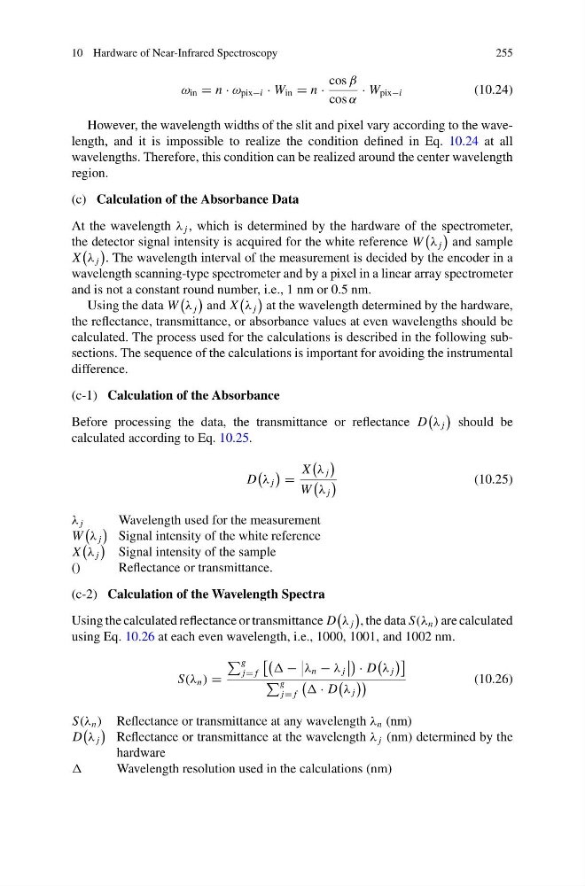
ω in = n · ω pix−i · W in = n ·
cos β
cos α
· W pix−i
(10.24)
However, the wavelength widths of the slit and pixel vary according to the wavelength, and it is impossible to realize the condition defined in Eq. 10.24 at all
wavelengths. Therefore, this condition can be realized around the center wavelength
region.
(c) Calculation of the Absorbance Data
At the wavelength λ j , which is determined by the hardware of the spectrometer,
the detector signal intensity is acquired for the white reference W
λ j
and sample
X
λ j
. The wavelength interval of the measurement is decided by the encoder in a
wavelength scanning-type spectrometer and by a pixel in a linear array spectrometer
and is not a constant round number, i.e., 1 nm or 0.5 nm.
Using the data W
λ j
and X
λ j
at the wavelength determined by the hardware,
the reflectance, transmittance, or absorbance values at even wavelengths should be
calculated. The process used for the calculations is described in the following subsections. The sequence of the calculations is important for avoiding the instrumental
difference.
(c-1) Calculation of the Absorbance
Before processing the data, the transmittance or reflectance D
λ j
should be
calculated according to Eq. 10.25.
D
λ j
=
X
λ j
W
λ j
(10.25)
λ j
Wavelength used for the measurement
W
λ j
Signal intensity of the white reference
X
λ j
Signal intensity of the sample
()
Reflectance or transmittance.
(c-2) Calculation of the Wavelength Spectra
Using the calculated reflectance or transmittance D
λ j
, the data S(λ n ) are calculated
using Eq. 10.26 at each even wavelength, i.e., 1000, 1001, and 1002 nm.
S(λ n ) =
g
j= f
−
λ n − λ j
· D
λ j
g
j= f
· D
λ j
(10.26)
S(λ n ) Reflectance or transmittance at any wavelength λ n (nm)
D
λ j
Reflectance or transmittance at the wavelength λ j (nm) determined by the
hardware
Wavelength resolution used in the calculations (nm)
255
ω in = n · ω pix−i · W in = n ·
cos β
cos α
· W pix−i
(10.24)
However, the wavelength widths of the slit and pixel vary according to the wavelength, and it is impossible to realize the condition defined in Eq. 10.24 at all
wavelengths. Therefore, this condition can be realized around the center wavelength
region.
(c) Calculation of the Absorbance Data
At the wavelength λ j , which is determined by the hardware of the spectrometer,
the detector signal intensity is acquired for the white reference W
λ j
and sample
X
λ j
. The wavelength interval of the measurement is decided by the encoder in a
wavelength scanning-type spectrometer and by a pixel in a linear array spectrometer
and is not a constant round number, i.e., 1 nm or 0.5 nm.
Using the data W
λ j
and X
λ j
at the wavelength determined by the hardware,
the reflectance, transmittance, or absorbance values at even wavelengths should be
calculated. The process used for the calculations is described in the following subsections. The sequence of the calculations is important for avoiding the instrumental
difference.
(c-1) Calculation of the Absorbance
Before processing the data, the transmittance or reflectance D
λ j
should be
calculated according to Eq. 10.25.
D
λ j
=
X
λ j
W
λ j
(10.25)
λ j
Wavelength used for the measurement
W
λ j
Signal intensity of the white reference
X
λ j
Signal intensity of the sample
()
Reflectance or transmittance.
(c-2) Calculation of the Wavelength Spectra
Using the calculated reflectance or transmittance D
λ j
, the data S(λ n ) are calculated
using Eq. 10.26 at each even wavelength, i.e., 1000, 1001, and 1002 nm.
S(λ n ) =
g
j= f
−
λ n − λ j
· D
λ j
g
j= f
· D
λ j
(10.26)
S(λ n ) Reflectance or transmittance at any wavelength λ n (nm)
D
λ j
Reflectance or transmittance at the wavelength λ j (nm) determined by the
hardware
Wavelength resolution used in the calculations (nm)