

248
T. Okura
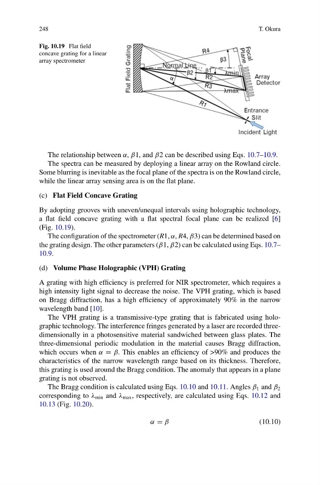
Fig. 10.19 Flat field
concave grating for a linear
array spectrometer
The relationship between α, β1, and β2 can be described using Eqs. 10.7–10.9.
The spectra can be measured by deploying a linear array on the Rowland circle.
Some blurring is inevitable as the focal plane of the spectra is on the Rowland circle,
while the linear array sensing area is on the flat plane.
(c) Flat Field Concave Grating
By adopting grooves with uneven/unequal intervals using holographic technology,
a flat field concave grating with a flat spectral focal plane can be realized [6]
(Fig. 10.19).
The configuration of the spectrometer (R1, α, R4, β3) can be determined based on
the grating design. The other parameters (β1, β2) can be calculated using Eqs. 10.7–
10.9.
(d) Volume Phase Holographic (VPH) Grating
A grating with high efficiency is preferred for NIR spectrometer, which requires a
high intensity light signal to decrease the noise. The VPH grating, which is based
on Bragg diffraction, has a high efficiency of approximately 90% in the narrow
wavelength band [10].
The VPH grating is a transmissive-type grating that is fabricated using holographic technology. The interference fringes generated by a laser are recorded threedimensionally in a photosensitive material sandwiched between glass plates. The
three-dimensional periodic modulation in the material causes Bragg diffraction,
which occurs when α = β. This enables an efficiency of >90% and produces the
characteristics of the narrow wavelength range based on its thickness. Therefore,
this grating is used around the Bragg condition. The anomaly that appears in a plane
grating is not observed.
The Bragg condition is calculated using Eqs. 10.10 and 10.11. Angles β 1 and β 2
corresponding to λ min and λ max , respectively, are calculated using Eqs. 10.12 and
10.13 (Fig. 10.20).
α = β
(10.10)
T. Okura
Fig. 10.19 Flat field
concave grating for a linear
array spectrometer
The relationship between α, β1, and β2 can be described using Eqs. 10.7–10.9.
The spectra can be measured by deploying a linear array on the Rowland circle.
Some blurring is inevitable as the focal plane of the spectra is on the Rowland circle,
while the linear array sensing area is on the flat plane.
(c) Flat Field Concave Grating
By adopting grooves with uneven/unequal intervals using holographic technology,
a flat field concave grating with a flat spectral focal plane can be realized [6]
(Fig. 10.19).
The configuration of the spectrometer (R1, α, R4, β3) can be determined based on
the grating design. The other parameters (β1, β2) can be calculated using Eqs. 10.7–
10.9.
(d) Volume Phase Holographic (VPH) Grating
A grating with high efficiency is preferred for NIR spectrometer, which requires a
high intensity light signal to decrease the noise. The VPH grating, which is based
on Bragg diffraction, has a high efficiency of approximately 90% in the narrow
wavelength band [10].
The VPH grating is a transmissive-type grating that is fabricated using holographic technology. The interference fringes generated by a laser are recorded threedimensionally in a photosensitive material sandwiched between glass plates. The
three-dimensional periodic modulation in the material causes Bragg diffraction,
which occurs when α = β. This enables an efficiency of >90% and produces the
characteristics of the narrow wavelength range based on its thickness. Therefore,
this grating is used around the Bragg condition. The anomaly that appears in a plane
grating is not observed.
The Bragg condition is calculated using Eqs. 10.10 and 10.11. Angles β 1 and β 2
corresponding to λ min and λ max , respectively, are calculated using Eqs. 10.12 and
10.13 (Fig. 10.20).
α = β
(10.10)