

5.3 Laser Specklometer (Microhematomyograph) …
387
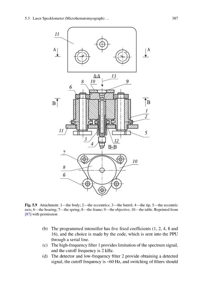
Fig. 5.9 Attachment: 1—the body; 2—the eccentrics; 3—the barrel; 4—the tip, 5—the eccentric
axis; 6—the bearing; 7—the spring; 8—the frame; 9—the objective; 10—the table. Reprinted from
[87] with permission
(b) The programmed intensifier has five fixed coefficients (1, 2, 4, 8 and
16), and the choice is made by the code, which is sent into the PPU
through a serial line.
(c) The high-frequency filter 1 provides limitation of the spectrum signal,
and the cutoff frequency is 2 kHz.
(d) The detector and low-frequency filter 2 provide obtaining a detected
signal, the cutoff frequency is ~60 Hz, and switching of filters should
387
Fig. 5.9 Attachment: 1—the body; 2—the eccentrics; 3—the barrel; 4—the tip, 5—the eccentric
axis; 6—the bearing; 7—the spring; 8—the frame; 9—the objective; 10—the table. Reprinted from
[87] with permission
(b) The programmed intensifier has five fixed coefficients (1, 2, 4, 8 and
16), and the choice is made by the code, which is sent into the PPU
through a serial line.
(c) The high-frequency filter 1 provides limitation of the spectrum signal,
and the cutoff frequency is 2 kHz.
(d) The detector and low-frequency filter 2 provide obtaining a detected
signal, the cutoff frequency is ~60 Hz, and switching of filters should