

262
3 Holographic Interferometry for Studying …
3.3.8 Optical Scheme of Laser-Holographic Complex
(Holographic Cardiograph)
Practical realization of the analyzed variants of optical schemes of the laserholographic complex (Figs. 3.34 and 3.43) appeared to be impossible, because
of the absence of the necessary elementary base: an electric shutter of the Glan
prism, half-wave plates, etc. Thereby, the necessity of principle scheme processing
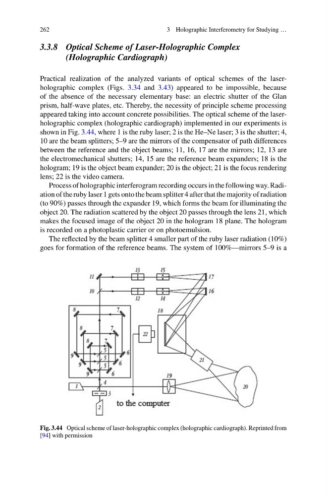
appeared taking into account concrete possibilities. The optical scheme of the laserholographic complex (holographic cardiograph) implemented in our experiments is
shown in Fig. 3.44, where 1 is the ruby laser; 2 is the He–Ne laser; 3 is the shutter; 4,
10 are the beam splitters; 5–9 are the mirrors of the compensator of path differences
between the reference and the object beams; 11, 16, 17 are the mirrors; 12, 13 are
the electromechanical shutters; 14, 15 are the reference beam expanders; 18 is the
hologram; 19 is the object beam expander; 20 is the object; 21 is the focus rendering
lens; 22 is the video camera.
Process of holographic interferogram recording occurs in the following way. Radiation of the ruby laser 1 gets onto the beam splitter 4 after that the majority of radiation
(to 90%) passes through the expander 19, which forms the beam for illuminating the
object 20. The radiation scattered by the object 20 passes through the lens 21, which
makes the focused image of the object 20 in the hologram 18 plane. The hologram
is recorded on a photoplastic carrier or on photoemulsion.
The reflected by the beam splitter 4 smaller part of the ruby laser radiation (10%)
goes for formation of the reference beams. The system of 100%—mirrors 5–9 is a
Fig. 3.44 Optical scheme of laser-holographic complex (holographic cardiograph). Reprinted from
[94] with permission
3 Holographic Interferometry for Studying …
3.3.8 Optical Scheme of Laser-Holographic Complex
(Holographic Cardiograph)
Practical realization of the analyzed variants of optical schemes of the laserholographic complex (Figs. 3.34 and 3.43) appeared to be impossible, because
of the absence of the necessary elementary base: an electric shutter of the Glan
prism, half-wave plates, etc. Thereby, the necessity of principle scheme processing
appeared taking into account concrete possibilities. The optical scheme of the laserholographic complex (holographic cardiograph) implemented in our experiments is
shown in Fig. 3.44, where 1 is the ruby laser; 2 is the He–Ne laser; 3 is the shutter; 4,
10 are the beam splitters; 5–9 are the mirrors of the compensator of path differences
between the reference and the object beams; 11, 16, 17 are the mirrors; 12, 13 are
the electromechanical shutters; 14, 15 are the reference beam expanders; 18 is the
hologram; 19 is the object beam expander; 20 is the object; 21 is the focus rendering
lens; 22 is the video camera.
Process of holographic interferogram recording occurs in the following way. Radiation of the ruby laser 1 gets onto the beam splitter 4 after that the majority of radiation
(to 90%) passes through the expander 19, which forms the beam for illuminating the
object 20. The radiation scattered by the object 20 passes through the lens 21, which
makes the focused image of the object 20 in the hologram 18 plane. The hologram
is recorded on a photoplastic carrier or on photoemulsion.
The reflected by the beam splitter 4 smaller part of the ruby laser radiation (10%)
goes for formation of the reference beams. The system of 100%—mirrors 5–9 is a
Fig. 3.44 Optical scheme of laser-holographic complex (holographic cardiograph). Reprinted from
[94] with permission