

2.3 Holographic Study with Electrophysiological Control …
131
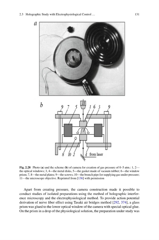
Fig. 2.28 Photo (a) and the scheme (b) of camera for creation of gas pressure of 0–5 atm.: 1, 2—
the optical windows; 3, 4—the metal disks, 5—the gasket made of vacuum rubber; 6—the window
prism; 7, 8—the metal plates; 9—the screws; 10—the brunch pipe for supplying gas under pressure;
11—the microscope objective. Reprinted from [136] with permission
Apart from creating pressure, the camera construction made it possible to
conduct studies of isolated preparations using the method of holographic interference microscopy and the electrophysiological method. To provide action potential
derivation of nerve fiber effect using Tasaki air bridges method [292, 374], a glass
prism was glued to the lower optical window of the camera with special optical glue.
On the prism in a drop of the physiological solution, the preparation under study was
131
Fig. 2.28 Photo (a) and the scheme (b) of camera for creation of gas pressure of 0–5 atm.: 1, 2—
the optical windows; 3, 4—the metal disks, 5—the gasket made of vacuum rubber; 6—the window
prism; 7, 8—the metal plates; 9—the screws; 10—the brunch pipe for supplying gas under pressure;
11—the microscope objective. Reprinted from [136] with permission
Apart from creating pressure, the camera construction made it possible to
conduct studies of isolated preparations using the method of holographic interference microscopy and the electrophysiological method. To provide action potential
derivation of nerve fiber effect using Tasaki air bridges method [292, 374], a glass
prism was glued to the lower optical window of the camera with special optical glue.
On the prism in a drop of the physiological solution, the preparation under study was