

74
2 Holographic Microscopy of Phase and Diffuse Objects …
vector in the result of scattering, ρ 2
x o +
d
= ρ 1 ( x 0 ), and also assuming that
U 01 ( x 0 ) is the slowly varying function. Then,
V 1 ( x i )V
∗
2 ( x i )
=
¨
U 01 ( x 0 )U
∗
02 (
x 0 )
ρ 1 ( x 0 )ρ 2 ( x
0 )
h( x i − M
x 0 , 0)
× h
∗
( x i − M
x 0 , d z )}d
2
x 0 d
2
x
0
=
U 01
x i
M
2
exp
iφ
x i
M
c(
d 0 , d z ),
(2.11)
where
c(
d 0 , d z ) =
1
M 2
h( x i , 0)h
∗
( x i − M
d 0 , d z )d
2
x i .
(2.12)
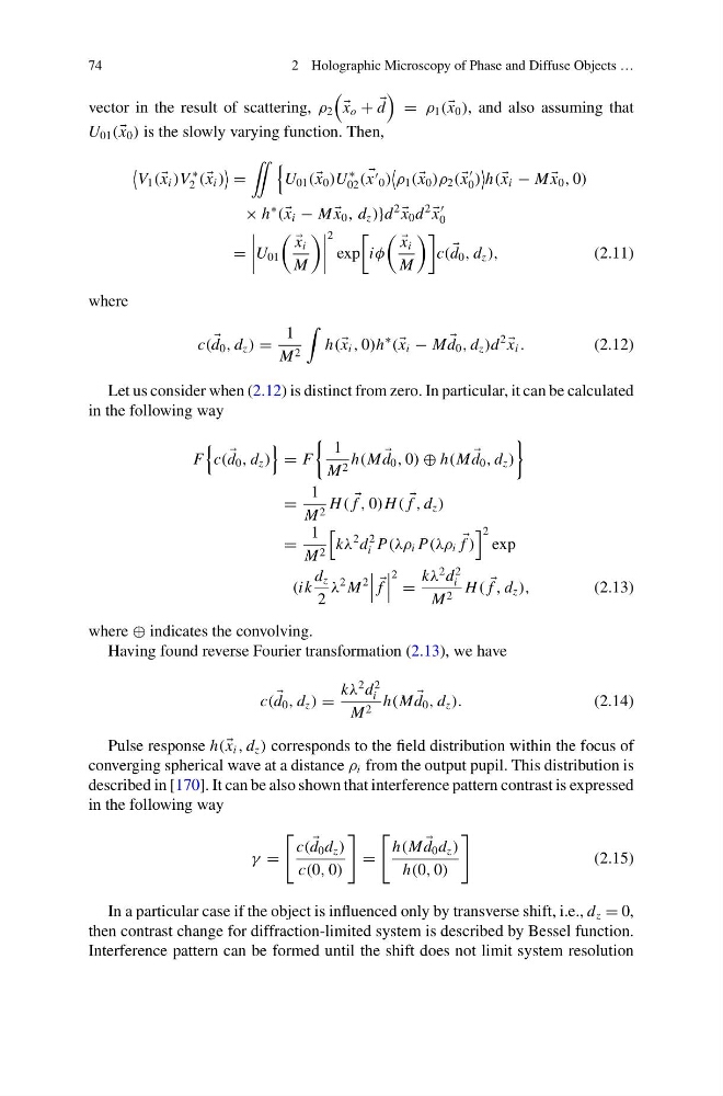
Let us consider when (2.12) is distinct from zero. In particular, it can be calculated
in the following way
F
c(
d 0 , d z )
= F
1
M 2 h(M
d 0 , 0) ⊕ h(M
d 0 , d z )
=
1
M 2 H (
f , 0)H (
f , d z )
=
1
M 2
kλ
2 d
2
i P(λρ i P(λρ i
f )
2
exp
(ik
d z
2
λ
2 M
2
f
2 =
kλ
2 d
2
i
M 2 H (
f , d z ),
(2.13)
where ⊕ indicates the convolving.
Having found reverse Fourier transformation (2.13), we have
c(
d 0 , d z ) =
kλ
2 d
2
i
M 2 h(M
d 0 , d z ).
(2.14)
Pulse response h( x i , d z ) corresponds to the field distribution within the focus of
converging spherical wave at a distance ρ i from the output pupil. This distribution is
described in [170]. It can be also shown that interference pattern contrast is expressed
in the following way
γ =
c(
d 0 d z )
c(0, 0)
=
h(M
d 0 d z )
h(0, 0)
(2.15)
In a particular case if the object is influenced only by transverse shift, i.e., d z = 0,
then contrast change for diffraction-limited system is described by Bessel function.
Interference pattern can be formed until the shift does not limit system resolution
2 Holographic Microscopy of Phase and Diffuse Objects …
vector in the result of scattering, ρ 2
x o +
d
= ρ 1 ( x 0 ), and also assuming that
U 01 ( x 0 ) is the slowly varying function. Then,
V 1 ( x i )V
∗
2 ( x i )
=
¨
U 01 ( x 0 )U
∗
02 (
x 0 )
ρ 1 ( x 0 )ρ 2 ( x
0 )
h( x i − M
x 0 , 0)
× h
∗
( x i − M
x 0 , d z )}d
2
x 0 d
2
x
0
=
U 01
x i
M
2
exp
iφ
x i
M
c(
d 0 , d z ),
(2.11)
where
c(
d 0 , d z ) =
1
M 2
h( x i , 0)h
∗
( x i − M
d 0 , d z )d
2
x i .
(2.12)
Let us consider when (2.12) is distinct from zero. In particular, it can be calculated
in the following way
F
c(
d 0 , d z )
= F
1
M 2 h(M
d 0 , 0) ⊕ h(M
d 0 , d z )
=
1
M 2 H (
f , 0)H (
f , d z )
=
1
M 2
kλ
2 d
2
i P(λρ i P(λρ i
f )
2
exp
(ik
d z
2
λ
2 M
2
f
2 =
kλ
2 d
2
i
M 2 H (
f , d z ),
(2.13)
where ⊕ indicates the convolving.
Having found reverse Fourier transformation (2.13), we have
c(
d 0 , d z ) =
kλ
2 d
2
i
M 2 h(M
d 0 , d z ).
(2.14)
Pulse response h( x i , d z ) corresponds to the field distribution within the focus of
converging spherical wave at a distance ρ i from the output pupil. This distribution is
described in [170]. It can be also shown that interference pattern contrast is expressed
in the following way
γ =
c(
d 0 d z )
c(0, 0)
=
h(M
d 0 d z )
h(0, 0)
(2.15)
In a particular case if the object is influenced only by transverse shift, i.e., d z = 0,
then contrast change for diffraction-limited system is described by Bessel function.
Interference pattern can be formed until the shift does not limit system resolution