

8.3 Keyhole and Weld Pool Dynamics in Welding with Filler Wires
215
8.3.4 Transient Keyhole and Weld Pool Behaviors Under
Contact Transition Conditions
Contact transition refers to the contact between the metallic liquid at the end of the
wire and the surface of the weld pool for the purpose transition. In this transition
condition, the connection between the wire and the weld pool is normally called
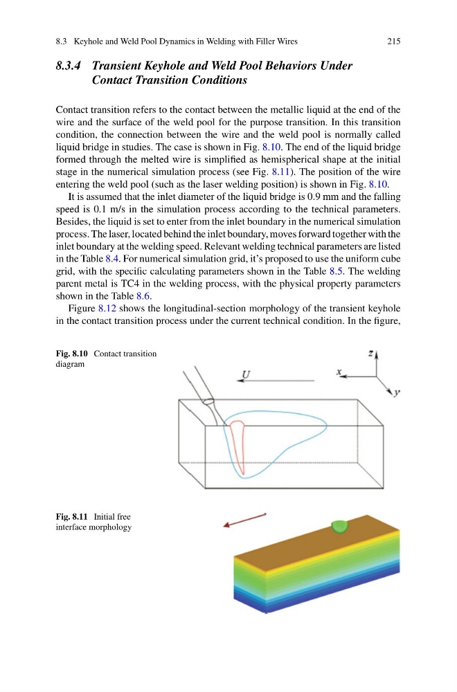
liquid bridge in studies. The case is shown in Fig. 8.10. The end of the liquid bridge
formed through the melted wire is simplified as hemispherical shape at the initial
stage in the numerical simulation process (see Fig. 8.11). The position of the wire
entering the weld pool (such as the laser welding position) is shown in Fig. 8.10.
It is assumed that the inlet diameter of the liquid bridge is 0.9 mm and the falling
speed is 0.1 m/s in the simulation process according to the technical parameters.
Besides, the liquid is set to enter from the inlet boundary in the numerical simulation
process. The laser, located behind the inlet boundary, moves forward together with the
inlet boundary at the welding speed. Relevant welding technical parameters are listed
in the Table 8.4. For numerical simulation grid, it’s proposed to use the uniform cube
grid, with the specific calculating parameters shown in the Table 8.5. The welding
parent metal is TC4 in the welding process, with the physical property parameters
shown in the Table 8.6.
Figure 8.12 shows the longitudinal-section morphology of the transient keyhole
in the contact transition process under the current technical condition. In the figure,
Fig. 8.10 Contact transition
diagram
Fig. 8.11 Initial free
interface morphology
215
8.3.4 Transient Keyhole and Weld Pool Behaviors Under
Contact Transition Conditions
Contact transition refers to the contact between the metallic liquid at the end of the
wire and the surface of the weld pool for the purpose transition. In this transition
condition, the connection between the wire and the weld pool is normally called
liquid bridge in studies. The case is shown in Fig. 8.10. The end of the liquid bridge
formed through the melted wire is simplified as hemispherical shape at the initial
stage in the numerical simulation process (see Fig. 8.11). The position of the wire
entering the weld pool (such as the laser welding position) is shown in Fig. 8.10.
It is assumed that the inlet diameter of the liquid bridge is 0.9 mm and the falling
speed is 0.1 m/s in the simulation process according to the technical parameters.
Besides, the liquid is set to enter from the inlet boundary in the numerical simulation
process. The laser, located behind the inlet boundary, moves forward together with the
inlet boundary at the welding speed. Relevant welding technical parameters are listed
in the Table 8.4. For numerical simulation grid, it’s proposed to use the uniform cube
grid, with the specific calculating parameters shown in the Table 8.5. The welding
parent metal is TC4 in the welding process, with the physical property parameters
shown in the Table 8.6.
Figure 8.12 shows the longitudinal-section morphology of the transient keyhole
in the contact transition process under the current technical condition. In the figure,
Fig. 8.10 Contact transition
diagram
Fig. 8.11 Initial free
interface morphology