

9.6 Results for 4D-Level 8
235
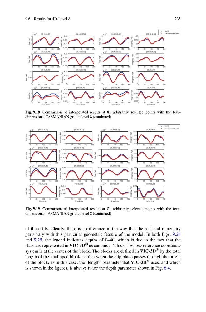
Fig. 9.18 Comparison of interpolated results at 81 arbitrarily selected points with the fourdimensional TASMANIAN grid at level 8 (continued)
Fig. 9.19 Comparison of interpolated results at 81 arbitrarily selected points with the fourdimensional TASMANIAN grid at level 8 (continued)
of these fits. Clearly, there is a difference in the way that the real and imaginary
parts vary with this particular geometric feature of the model. In both Figs. 9.24
and 9.25, the legend indicates depths of 0–40, which is due to the fact that the
slabs are represented in VIC-3D ® as canonical ‘blocks,’ whose reference coordinate
system is at the center of the block. The blocks are defined in VIC-3D ® by the total
length of the unclipped block, so that when the clip plane passes through the origin
of the block, as in this case, the ‘length’ parameter that VIC-3D ® uses, and which
is shown in the figures, is always twice the depth parameter shown in Fig. 6.4.
235
Fig. 9.18 Comparison of interpolated results at 81 arbitrarily selected points with the fourdimensional TASMANIAN grid at level 8 (continued)
Fig. 9.19 Comparison of interpolated results at 81 arbitrarily selected points with the fourdimensional TASMANIAN grid at level 8 (continued)
of these fits. Clearly, there is a difference in the way that the real and imaginary
parts vary with this particular geometric feature of the model. In both Figs. 9.24
and 9.25, the legend indicates depths of 0–40, which is due to the fact that the
slabs are represented in VIC-3D ® as canonical ‘blocks,’ whose reference coordinate
system is at the center of the block. The blocks are defined in VIC-3D ® by the total
length of the unclipped block, so that when the clip plane passes through the origin
of the block, as in this case, the ‘length’ parameter that VIC-3D ® uses, and which
is shown in the figures, is always twice the depth parameter shown in Fig. 6.4.