

198
8 A Model for Microstructure Characterization
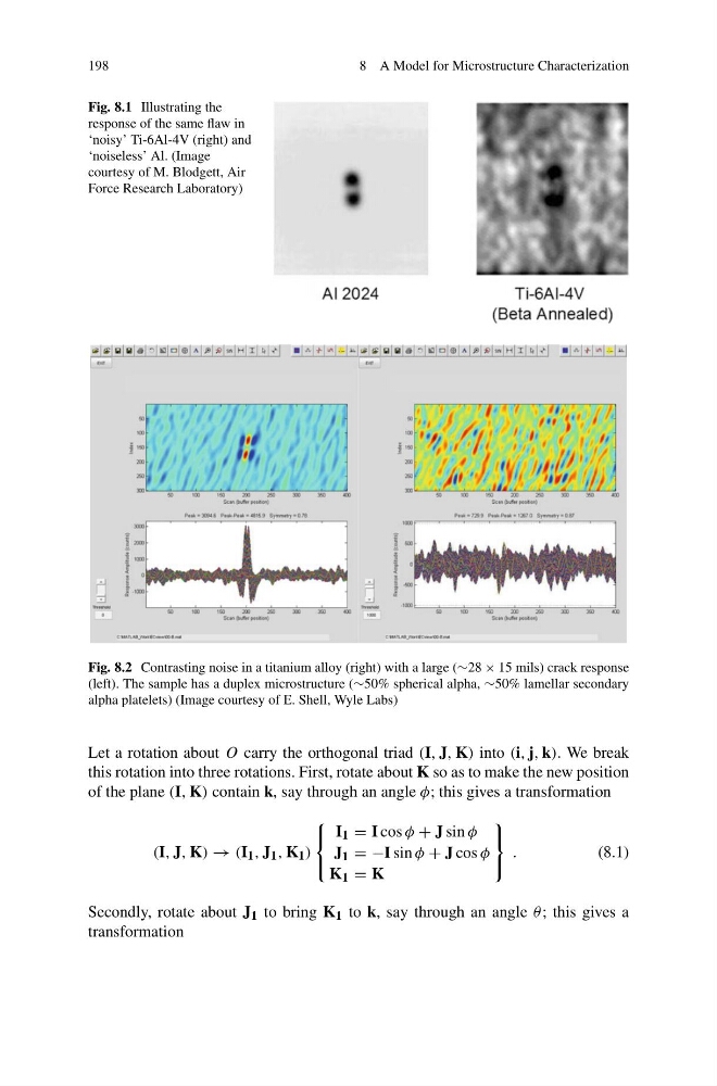
Fig. 8.1 Illustrating the
response of the same flaw in
‘noisy’ Ti-6Al-4V (right) and
‘noiseless’ Al. (Image
courtesy of M. Blodgett, Air
Force Research Laboratory)
Fig. 8.2 Contrasting noise in a titanium alloy (right) with a large (∼28 × 15 mils) crack response
(left). The sample has a duplex microstructure (∼50% spherical alpha, ∼50% lamellar secondary
alpha platelets) (Image courtesy of E. Shell, Wyle Labs)
Let a rotation about O carry the orthogonal triad (I, J, K) into (i, j, k). We break
this rotation into three rotations. First, rotate about K so as to make the new position
of the plane (I, K) contain k, say through an angle φ; this gives a transformation
(I, J, K) → (I 1 , J 1 , K 1 )
⎧
⎨
⎩
I 1 = I cos φ + J sin φ
J 1 = −I sin φ + J cos φ
K 1 = K
⎫
⎬
⎭
.
(8.1)
Secondly, rotate about J 1 to bring K 1 to k, say through an angle θ ; this gives a
transformation
8 A Model for Microstructure Characterization
Fig. 8.1 Illustrating the
response of the same flaw in
‘noisy’ Ti-6Al-4V (right) and
‘noiseless’ Al. (Image
courtesy of M. Blodgett, Air
Force Research Laboratory)
Fig. 8.2 Contrasting noise in a titanium alloy (right) with a large (∼28 × 15 mils) crack response
(left). The sample has a duplex microstructure (∼50% spherical alpha, ∼50% lamellar secondary
alpha platelets) (Image courtesy of E. Shell, Wyle Labs)
Let a rotation about O carry the orthogonal triad (I, J, K) into (i, j, k). We break
this rotation into three rotations. First, rotate about K so as to make the new position
of the plane (I, K) contain k, say through an angle φ; this gives a transformation
(I, J, K) → (I 1 , J 1 , K 1 )
⎧
⎨
⎩
I 1 = I cos φ + J sin φ
J 1 = −I sin φ + J cos φ
K 1 = K
⎫
⎬
⎭
.
(8.1)
Secondly, rotate about J 1 to bring K 1 to k, say through an angle θ ; this gives a
transformation