

4.2 Multi-Pixel Interdigitated Photoconductive Emitters
73
components, and additional alignment steps were required in order to optimise the
signal-to-noise ratio of the THz emission at all angles. A source of inspiration for
an alternative method of polarisation rotation can come from the both the results
of Chap. 3, and the concept of sub-wavelength sources interacting in the far-field.
An electromagnetic wave with an arbitrary polarisation state can be resolved into
two orthogonally polarised components, and the polarisation state produced by an
interdigitated PCE can be varied between two orthogonal polarisations by changing
its orientation by 90
◦ . By positioning small interdigitated structures with orientations
that vary by 90
◦ in close proximity, and photoexciting both orientations with the
same pump beam, the resulting polarisation state of the THz in the far-field may be
controlled if the emission strength of the orthogonally oriented interdigitated PCEs
can be controlled.
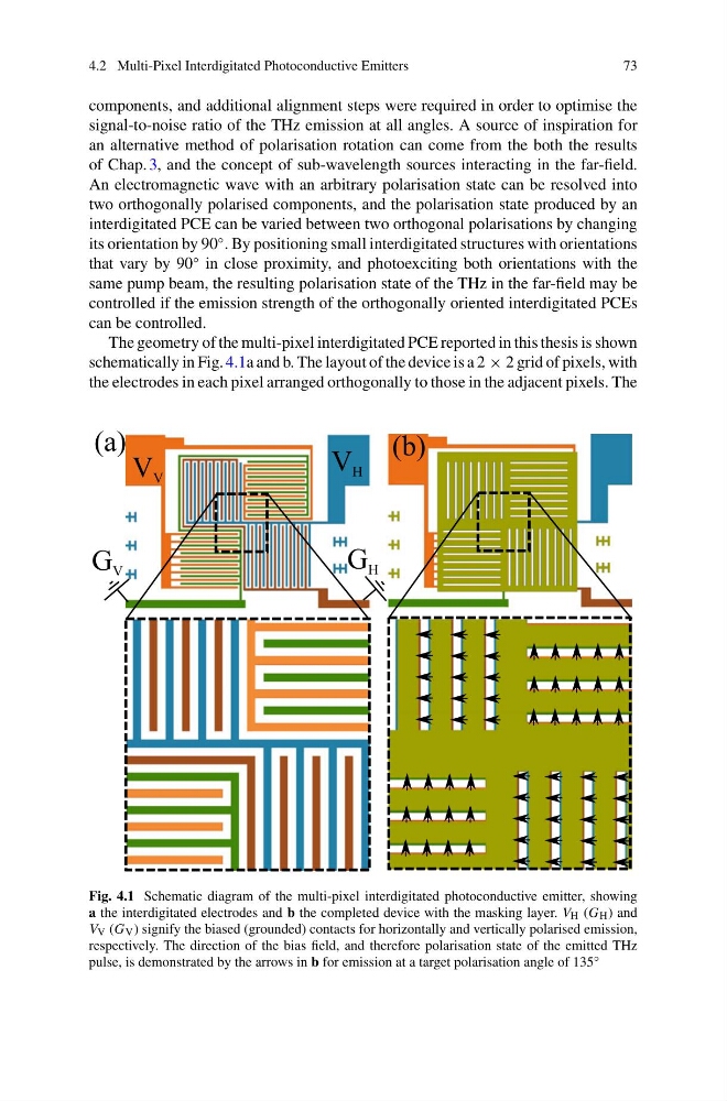
The geometry of the multi-pixel interdigitated PCE reported in this thesis is shown
schematically in Fig. 4.1a and b. The layout of the device is a 2 × 2 grid of pixels, with
the electrodes in each pixel arranged orthogonally to those in the adjacent pixels. The
Fig. 4.1 Schematic diagram of the multi-pixel interdigitated photoconductive emitter, showing
a the interdigitated electrodes and b the completed device with the masking layer. V H (G H ) and
V V (G V ) signify the biased (grounded) contacts for horizontally and vertically polarised emission,
respectively. The direction of the bias field, and therefore polarisation state of the emitted THz
pulse, is demonstrated by the arrows in b for emission at a target polarisation angle of 135 ◦
73
components, and additional alignment steps were required in order to optimise the
signal-to-noise ratio of the THz emission at all angles. A source of inspiration for
an alternative method of polarisation rotation can come from the both the results
of Chap. 3, and the concept of sub-wavelength sources interacting in the far-field.
An electromagnetic wave with an arbitrary polarisation state can be resolved into
two orthogonally polarised components, and the polarisation state produced by an
interdigitated PCE can be varied between two orthogonal polarisations by changing
its orientation by 90
◦ . By positioning small interdigitated structures with orientations
that vary by 90
◦ in close proximity, and photoexciting both orientations with the
same pump beam, the resulting polarisation state of the THz in the far-field may be
controlled if the emission strength of the orthogonally oriented interdigitated PCEs
can be controlled.
The geometry of the multi-pixel interdigitated PCE reported in this thesis is shown
schematically in Fig. 4.1a and b. The layout of the device is a 2 × 2 grid of pixels, with
the electrodes in each pixel arranged orthogonally to those in the adjacent pixels. The
Fig. 4.1 Schematic diagram of the multi-pixel interdigitated photoconductive emitter, showing
a the interdigitated electrodes and b the completed device with the masking layer. V H (G H ) and
V V (G V ) signify the biased (grounded) contacts for horizontally and vertically polarised emission,
respectively. The direction of the bias field, and therefore polarisation state of the emitted THz
pulse, is demonstrated by the arrows in b for emission at a target polarisation angle of 135 ◦