

3.2 Rotatable-Polarisation Terahertz Time-Domain Spectrometer
51
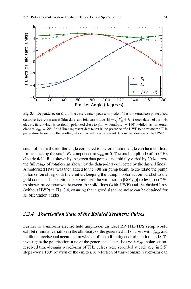
Fig. 3.4 Dependence on ψ em of the time-domain peak amplitude of the horizontal component (red
data), vertical component (blue data) and total amplitude |E| =
E 2
H + E 2
V (green data), of the THz
electric field, which is vertically polarized close to ψ em = 0 and ψ em = 180 ◦ , while it is horizontal
close to ψ em = 90 ◦ . Solid lines represent data taken in the presence of a HWP to co-rotate the THz
generation beam with the emitter, whilst dashed lines represent data in the absence of the HWP
small offset in the emitter angle compared to the orientation angle can be identified,
for instance by the small E x component at ψ em = 0. The total amplitude of the THz
electric field |E| is shown by the green data points, and initially varied by 20 % across
the full range of rotation (as shown by the data points connected by the dashed lines).
A motorised HWP was then added to the 800 nm pump beam, to co-rotate the pump
polarization along with the emitter, keeping the pump’s polarization parallel to the
gold contacts. This optional step reduced the variation in |E(ψ em )| to less than 7 %,
as shown by comparison between the solid lines (with HWP) and the dashed lines
(without HWP) in Fig. 3.4, ensuring that a good signal-to-noise can be obtained for
all orientation angles.
3.2.4 Polarisation State of the Rotated Terahertz Pulses
Further to a uniform electric field amplitude, an ideal RP-THz-TDS setup would
exhibit minimal variation in the ellipticity of the generated THz pulses with ψ em , and
facilitate precise and accurate knowledge of the ellipticity and orientation angle. To
investigate the polarisation state of the generated THz pulses with ψ em , polarisationresolved time-domain waveforms of THz pulses were recorded at each ψ em in 2.5
◦
steps over a 180
◦ rotation of the emitter. A selection of time-domain waveforms can
51
Fig. 3.4 Dependence on ψ em of the time-domain peak amplitude of the horizontal component (red
data), vertical component (blue data) and total amplitude |E| =
E 2
H + E 2
V (green data), of the THz
electric field, which is vertically polarized close to ψ em = 0 and ψ em = 180 ◦ , while it is horizontal
close to ψ em = 90 ◦ . Solid lines represent data taken in the presence of a HWP to co-rotate the THz
generation beam with the emitter, whilst dashed lines represent data in the absence of the HWP
small offset in the emitter angle compared to the orientation angle can be identified,
for instance by the small E x component at ψ em = 0. The total amplitude of the THz
electric field |E| is shown by the green data points, and initially varied by 20 % across
the full range of rotation (as shown by the data points connected by the dashed lines).
A motorised HWP was then added to the 800 nm pump beam, to co-rotate the pump
polarization along with the emitter, keeping the pump’s polarization parallel to the
gold contacts. This optional step reduced the variation in |E(ψ em )| to less than 7 %,
as shown by comparison between the solid lines (with HWP) and the dashed lines
(without HWP) in Fig. 3.4, ensuring that a good signal-to-noise can be obtained for
all orientation angles.
3.2.4 Polarisation State of the Rotated Terahertz Pulses
Further to a uniform electric field amplitude, an ideal RP-THz-TDS setup would
exhibit minimal variation in the ellipticity of the generated THz pulses with ψ em , and
facilitate precise and accurate knowledge of the ellipticity and orientation angle. To
investigate the polarisation state of the generated THz pulses with ψ em , polarisationresolved time-domain waveforms of THz pulses were recorded at each ψ em in 2.5
◦
steps over a 180
◦ rotation of the emitter. A selection of time-domain waveforms can