

48
3 Rotatable-Polarisation Terahertz Time-Domain Spectroscopy of Anisotropic Media
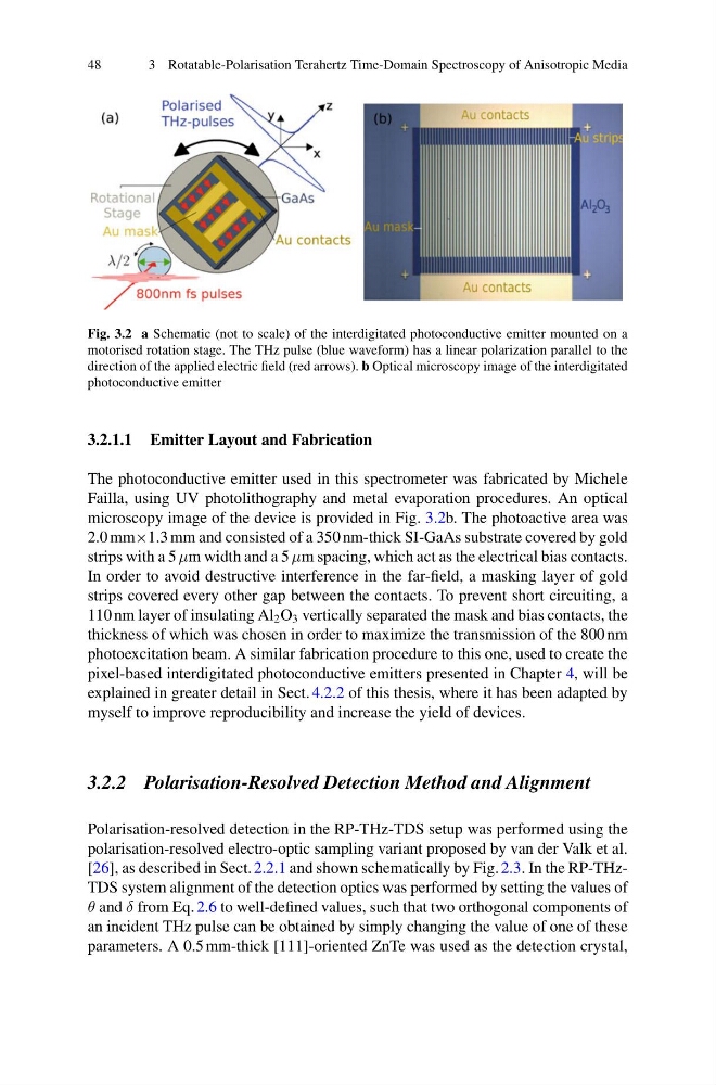
Fig. 3.2 a Schematic (not to scale) of the interdigitated photoconductive emitter mounted on a
motorised rotation stage. The THz pulse (blue waveform) has a linear polarization parallel to the
direction of the applied electric field (red arrows). b Optical microscopy image of the interdigitated
photoconductive emitter
3.2.1.1 Emitter Layout and Fabrication
The photoconductive emitter used in this spectrometer was fabricated by Michele
Failla, using UV photolithography and metal evaporation procedures. An optical
microscopy image of the device is provided in Fig. 3.2b. The photoactive area was
2.0 mm×1.3 mm and consisted of a 350 nm-thick SI-GaAs substrate covered by gold
strips with a 5 μm width and a 5 μm spacing, which act as the electrical bias contacts.
In order to avoid destructive interference in the far-field, a masking layer of gold
strips covered every other gap between the contacts. To prevent short circuiting, a
110 nm layer of insulating Al 2 O 3 vertically separated the mask and bias contacts, the
thickness of which was chosen in order to maximize the transmission of the 800 nm
photoexcitation beam. A similar fabrication procedure to this one, used to create the
pixel-based interdigitated photoconductive emitters presented in Chapter 4, will be
explained in greater detail in Sect. 4.2.2 of this thesis, where it has been adapted by
myself to improve reproducibility and increase the yield of devices.
3.2.2 Polarisation-Resolved Detection Method and Alignment
Polarisation-resolved detection in the RP-THz-TDS setup was performed using the
polarisation-resolved electro-optic sampling variant proposed by van der Valk et al.
[26], as described in Sect. 2.2.1 and shown schematically by Fig. 2.3. In the RP-THzTDS system alignment of the detection optics was performed by setting the values of
θ and δ from Eq. 2.6 to well-defined values, such that two orthogonal components of
an incident THz pulse can be obtained by simply changing the value of one of these
parameters. A 0.5 mm-thick [111]-oriented ZnTe was used as the detection crystal,
3 Rotatable-Polarisation Terahertz Time-Domain Spectroscopy of Anisotropic Media
Fig. 3.2 a Schematic (not to scale) of the interdigitated photoconductive emitter mounted on a
motorised rotation stage. The THz pulse (blue waveform) has a linear polarization parallel to the
direction of the applied electric field (red arrows). b Optical microscopy image of the interdigitated
photoconductive emitter
3.2.1.1 Emitter Layout and Fabrication
The photoconductive emitter used in this spectrometer was fabricated by Michele
Failla, using UV photolithography and metal evaporation procedures. An optical
microscopy image of the device is provided in Fig. 3.2b. The photoactive area was
2.0 mm×1.3 mm and consisted of a 350 nm-thick SI-GaAs substrate covered by gold
strips with a 5 μm width and a 5 μm spacing, which act as the electrical bias contacts.
In order to avoid destructive interference in the far-field, a masking layer of gold
strips covered every other gap between the contacts. To prevent short circuiting, a
110 nm layer of insulating Al 2 O 3 vertically separated the mask and bias contacts, the
thickness of which was chosen in order to maximize the transmission of the 800 nm
photoexcitation beam. A similar fabrication procedure to this one, used to create the
pixel-based interdigitated photoconductive emitters presented in Chapter 4, will be
explained in greater detail in Sect. 4.2.2 of this thesis, where it has been adapted by
myself to improve reproducibility and increase the yield of devices.
3.2.2 Polarisation-Resolved Detection Method and Alignment
Polarisation-resolved detection in the RP-THz-TDS setup was performed using the
polarisation-resolved electro-optic sampling variant proposed by van der Valk et al.
[26], as described in Sect. 2.2.1 and shown schematically by Fig. 2.3. In the RP-THzTDS system alignment of the detection optics was performed by setting the values of
θ and δ from Eq. 2.6 to well-defined values, such that two orthogonal components of
an incident THz pulse can be obtained by simply changing the value of one of these
parameters. A 0.5 mm-thick [111]-oriented ZnTe was used as the detection crystal,