

94
5 High-Field Terahertz Time-Domain Spectroscopy …
interferes constructively as the pump pulse propagates through the crystal, and exits
the crystal at a face cut at the same angle, θ C .
5.2.1.1 Obtaining the Pulse Front Tilt
A number of methods are available for obtaining a tilt to the pulse front of the optical
pulse, which include using a diffraction grating and one [50] or two [51] lenses, or by
patterning a grating structure directly onto the generation crystal [52]. The method
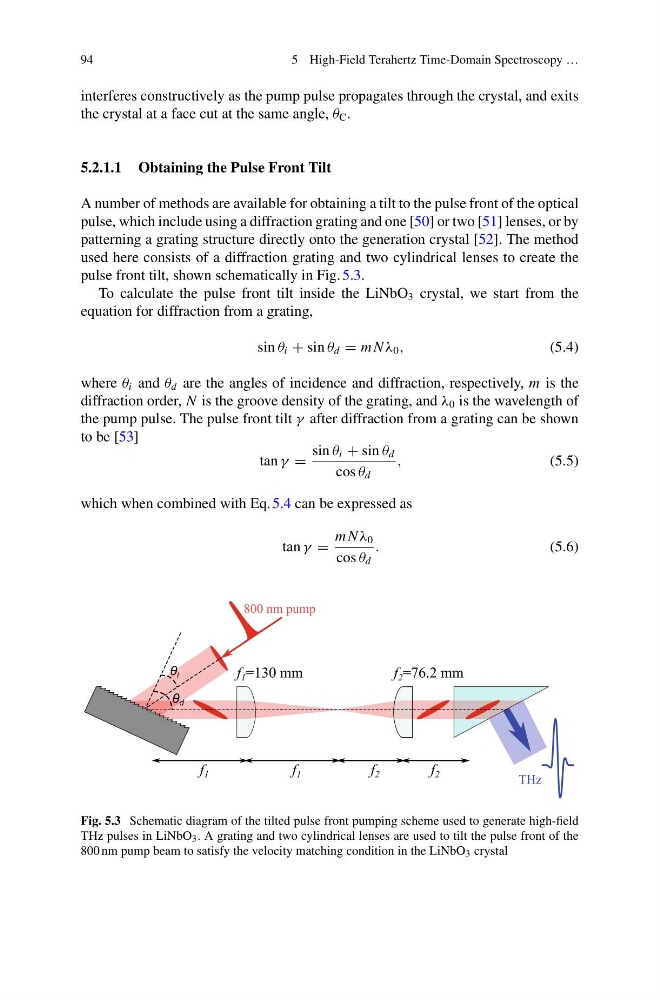
used here consists of a diffraction grating and two cylindrical lenses to create the
pulse front tilt, shown schematically in Fig. 5.3.
To calculate the pulse front tilt inside the LiNbO 3 crystal, we start from the
equation for diffraction from a grating,
sin θ i + sin θ d = m N λ 0 ,
(5.4)
where θ i and θ d are the angles of incidence and diffraction, respectively, m is the
diffraction order, N is the groove density of the grating, and λ 0 is the wavelength of
the pump pulse. The pulse front tilt γ after diffraction from a grating can be shown
to be [53]
tan γ =
sin θ i + sin θ d
cos θ d
,
(5.5)
which when combined with Eq. 5.4 can be expressed as
tan γ =
m N λ 0
cos θ d
.
(5.6)
Fig. 5.3 Schematic diagram of the tilted pulse front pumping scheme used to generate high-field
THz pulses in LiNbO 3 . A grating and two cylindrical lenses are used to tilt the pulse front of the
800 nm pump beam to satisfy the velocity matching condition in the LiNbO 3 crystal
5 High-Field Terahertz Time-Domain Spectroscopy …
interferes constructively as the pump pulse propagates through the crystal, and exits
the crystal at a face cut at the same angle, θ C .
5.2.1.1 Obtaining the Pulse Front Tilt
A number of methods are available for obtaining a tilt to the pulse front of the optical
pulse, which include using a diffraction grating and one [50] or two [51] lenses, or by
patterning a grating structure directly onto the generation crystal [52]. The method
used here consists of a diffraction grating and two cylindrical lenses to create the
pulse front tilt, shown schematically in Fig. 5.3.
To calculate the pulse front tilt inside the LiNbO 3 crystal, we start from the
equation for diffraction from a grating,
sin θ i + sin θ d = m N λ 0 ,
(5.4)
where θ i and θ d are the angles of incidence and diffraction, respectively, m is the
diffraction order, N is the groove density of the grating, and λ 0 is the wavelength of
the pump pulse. The pulse front tilt γ after diffraction from a grating can be shown
to be [53]
tan γ =
sin θ i + sin θ d
cos θ d
,
(5.5)
which when combined with Eq. 5.4 can be expressed as
tan γ =
m N λ 0
cos θ d
.
(5.6)
Fig. 5.3 Schematic diagram of the tilted pulse front pumping scheme used to generate high-field
THz pulses in LiNbO 3 . A grating and two cylindrical lenses are used to tilt the pulse front of the
800 nm pump beam to satisfy the velocity matching condition in the LiNbO 3 crystal