

226
12 Cryptocurrencies
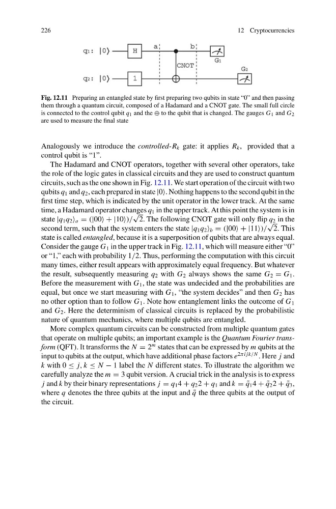
Fig. 12.11 Preparing an entangled state by first preparing two qubits in state “0” and then passing
them through a quantum circuit, composed of a Hadamard and a CNOT gate. The small full circle
is connected to the control qubit q 1 and the ⊕ to the qubit that is changed. The gauges G 1 and G 2
are used to measure the final state
Analogously we introduce the controlled-R k gate: it applies R k , provided that a
control qubit is “1”.
The Hadamard and CNOT operators, together with several other operators, take
the role of the logic gates in classical circuits and they are used to construct quantum
circuits, such as the one shown in Fig. 12.11. We start operation of the circuit with two
qubits q 1 and q 2 , each prepared in state |0. Nothing happens to the second qubit in the
first time step, which is indicated by the unit operator in the lower track. At the same
time, a Hadamard operator changes q 1 in the upper track. At this point the system is in
state |q 1 q 2 a = (|00 + |10)/
√
2. The following CNOT gate will only flip q 2 in the
second term, such that the system enters the state |q 1 q 2 b = (|00 + |11)/
√
2. This
state is called entangled, because it is a superposition of qubits that are always equal.
Consider the gauge G 1 in the upper track in Fig. 12.11, which will measure either “0”
or “1,” each with probability 1/2. Thus, performing the computation with this circuit
many times, either result appears with approximately equal frequency. But whatever
the result, subsequently measuring q 2 with G 2 always shows the same G 2 = G 1 .
Before the measurement with G 1 , the state was undecided and the probabilities are
equal, but once we start measuring with G 1 , “the system decides” and then G 2 has
no other option than to follow G 1 . Note how entanglement links the outcome of G 1
and G 2 . Here the determinism of classical circuits is replaced by the probabilistic
nature of quantum mechanics, where multiple qubits are entangled.
More complex quantum circuits can be constructed from multiple quantum gates
that operate on multiple qubits; an important example is the Quantum Fourier transform (QFT). It transforms the N = 2
m states that can be expressed by m qubits at the
input to qubits at the output, which have additional phase factors e
2πi jk/N . Here j and
k with 0 ≤ j, k ≤ N − 1 label the N different states. To illustrate the algorithm we
carefully analyze the m = 3 qubit version. A crucial trick in the analysis is to express
j and k by their binary representations j = q 1 4 + q 2 2 + q 1 and k = ˜
q 1 4 + ˜
q 2 2 + ˜
q 3 ,
where q denotes the three qubits at the input and ˜
q the three qubits at the output of
the circuit.
12 Cryptocurrencies
Fig. 12.11 Preparing an entangled state by first preparing two qubits in state “0” and then passing
them through a quantum circuit, composed of a Hadamard and a CNOT gate. The small full circle
is connected to the control qubit q 1 and the ⊕ to the qubit that is changed. The gauges G 1 and G 2
are used to measure the final state
Analogously we introduce the controlled-R k gate: it applies R k , provided that a
control qubit is “1”.
The Hadamard and CNOT operators, together with several other operators, take
the role of the logic gates in classical circuits and they are used to construct quantum
circuits, such as the one shown in Fig. 12.11. We start operation of the circuit with two
qubits q 1 and q 2 , each prepared in state |0. Nothing happens to the second qubit in the
first time step, which is indicated by the unit operator in the lower track. At the same
time, a Hadamard operator changes q 1 in the upper track. At this point the system is in
state |q 1 q 2 a = (|00 + |10)/
√
2. The following CNOT gate will only flip q 2 in the
second term, such that the system enters the state |q 1 q 2 b = (|00 + |11)/
√
2. This
state is called entangled, because it is a superposition of qubits that are always equal.
Consider the gauge G 1 in the upper track in Fig. 12.11, which will measure either “0”
or “1,” each with probability 1/2. Thus, performing the computation with this circuit
many times, either result appears with approximately equal frequency. But whatever
the result, subsequently measuring q 2 with G 2 always shows the same G 2 = G 1 .
Before the measurement with G 1 , the state was undecided and the probabilities are
equal, but once we start measuring with G 1 , “the system decides” and then G 2 has
no other option than to follow G 1 . Note how entanglement links the outcome of G 1
and G 2 . Here the determinism of classical circuits is replaced by the probabilistic
nature of quantum mechanics, where multiple qubits are entangled.
More complex quantum circuits can be constructed from multiple quantum gates
that operate on multiple qubits; an important example is the Quantum Fourier transform (QFT). It transforms the N = 2
m states that can be expressed by m qubits at the
input to qubits at the output, which have additional phase factors e
2πi jk/N . Here j and
k with 0 ≤ j, k ≤ N − 1 label the N different states. To illustrate the algorithm we
carefully analyze the m = 3 qubit version. A crucial trick in the analysis is to express
j and k by their binary representations j = q 1 4 + q 2 2 + q 1 and k = ˜
q 1 4 + ˜
q 2 2 + ˜
q 3 ,
where q denotes the three qubits at the input and ˜
q the three qubits at the output of
the circuit.