

2.4 Genealogy of Memristor Devices
65
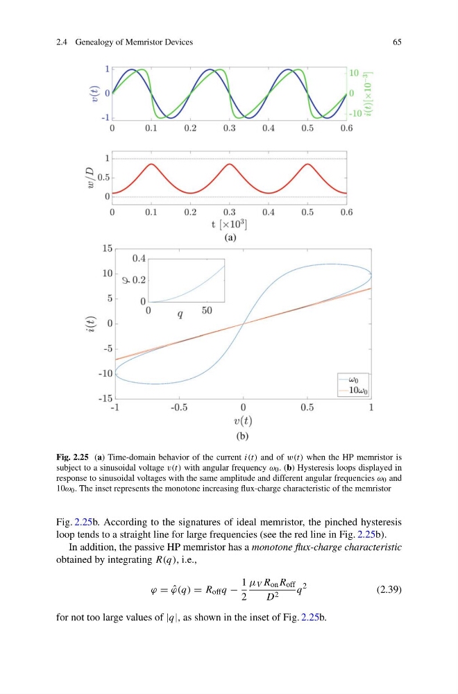
Fig. 2.25 (a) Time-domain behavior of the current i(t) and of w(t) when the HP memristor is
subject to a sinusoidal voltage v(t) with angular frequency ω 0 . (b) Hysteresis loops displayed in
response to sinusoidal voltages with the same amplitude and different angular frequencies ω 0 and
10ω 0 . The inset represents the monotone increasing flux-charge characteristic of the memristor
Fig. 2.25b. According to the signatures of ideal memristor, the pinched hysteresis
loop tends to a straight line for large frequencies (see the red line in Fig. 2.25b).
In addition, the passive HP memristor has a monotone flux-charge characteristic
obtained by integrating R(q), i.e.,
ϕ = ˆ
ϕ(q) = R off q −
1
2
μ V R on R off
D 2
q
2
(2.39)
for not too large values of |q|, as shown in the inset of Fig. 2.25b.
65
Fig. 2.25 (a) Time-domain behavior of the current i(t) and of w(t) when the HP memristor is
subject to a sinusoidal voltage v(t) with angular frequency ω 0 . (b) Hysteresis loops displayed in
response to sinusoidal voltages with the same amplitude and different angular frequencies ω 0 and
10ω 0 . The inset represents the monotone increasing flux-charge characteristic of the memristor
Fig. 2.25b. According to the signatures of ideal memristor, the pinched hysteresis
loop tends to a straight line for large frequencies (see the red line in Fig. 2.25b).
In addition, the passive HP memristor has a monotone flux-charge characteristic
obtained by integrating R(q), i.e.,
ϕ = ˆ
ϕ(q) = R off q −
1
2
μ V R on R off
D 2
q
2
(2.39)
for not too large values of |q|, as shown in the inset of Fig. 2.25b.