

2.2 Ideal Memristors and Non-volatile Memories
43
E
R
+
−
v
i
ˆ i(v)
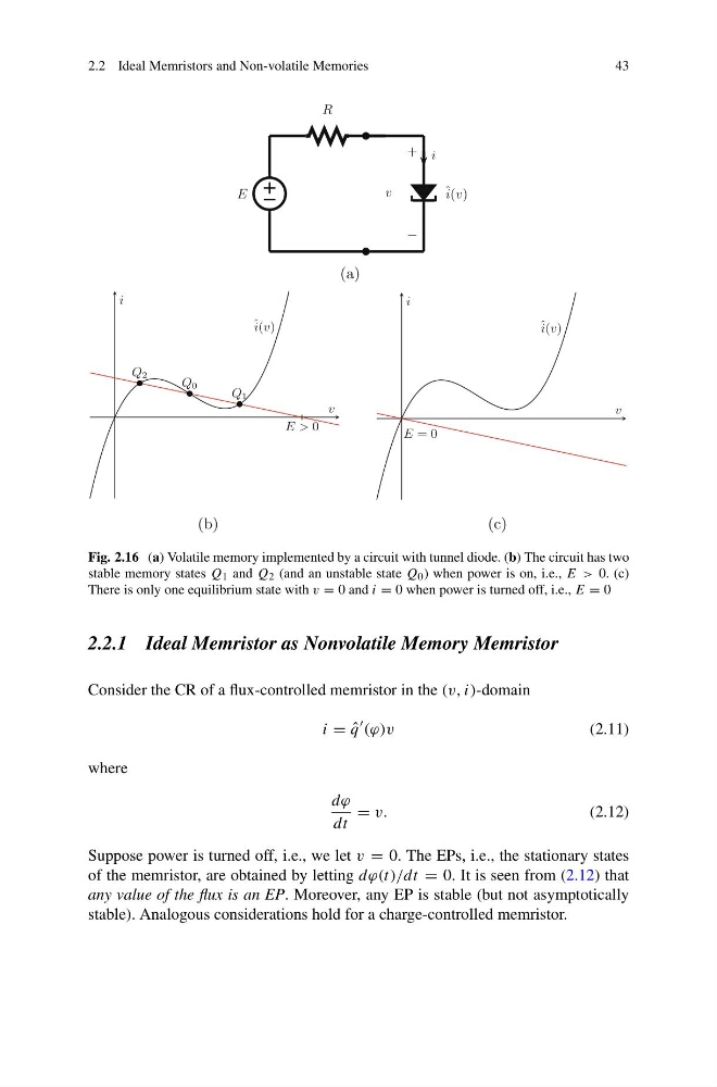
Fig. 2.16 (a) Volatile memory implemented by a circuit with tunnel diode. (b) The circuit has two
stable memory states Q 1 and Q 2 (and an unstable state Q 0 ) when power is on, i.e., E > 0. (c)
There is only one equilibrium state with v = 0 and i = 0 when power is turned off, i.e., E = 0
2.2.1 Ideal Memristor as Nonvolatile Memory Memristor
Consider the CR of a flux-controlled memristor in the (v, i)-domain
i = ˆ
q
(ϕ)v
(2.11)
where
dϕ
dt
= v.
(2.12)
Suppose power is turned off, i.e., we let v = 0. The EPs, i.e., the stationary states
of the memristor, are obtained by letting dϕ(t)/dt = 0. It is seen from (2.12) that
any value of the flux is an EP. Moreover, any EP is stable (but not asymptotically
stable). Analogous considerations hold for a charge-controlled memristor.
43
E
R
+
−
v
i
ˆ i(v)
Fig. 2.16 (a) Volatile memory implemented by a circuit with tunnel diode. (b) The circuit has two
stable memory states Q 1 and Q 2 (and an unstable state Q 0 ) when power is on, i.e., E > 0. (c)
There is only one equilibrium state with v = 0 and i = 0 when power is turned off, i.e., E = 0
2.2.1 Ideal Memristor as Nonvolatile Memory Memristor
Consider the CR of a flux-controlled memristor in the (v, i)-domain
i = ˆ
q
(ϕ)v
(2.11)
where
dϕ
dt
= v.
(2.12)
Suppose power is turned off, i.e., we let v = 0. The EPs, i.e., the stationary states
of the memristor, are obtained by letting dϕ(t)/dt = 0. It is seen from (2.12) that
any value of the flux is an EP. Moreover, any EP is stable (but not asymptotically
stable). Analogous considerations hold for a charge-controlled memristor.