

8.2 Memristor-Based Chaotic Circuit (MCC)
321
8.2 Memristor-Based Chaotic Circuit (MCC)
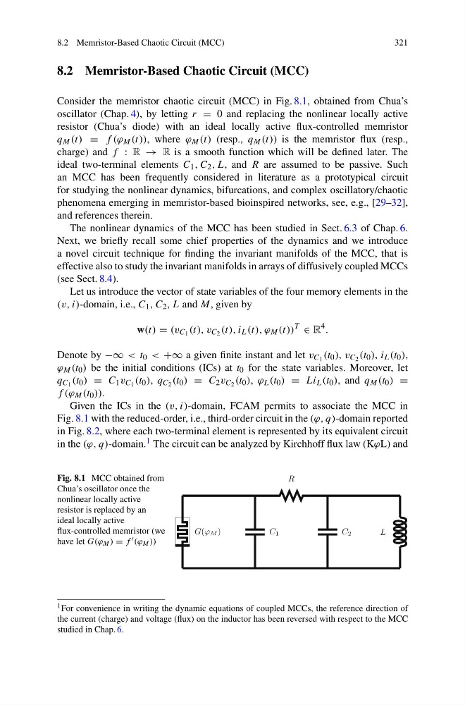
Consider the memristor chaotic circuit (MCC) in Fig. 8.1, obtained from Chua’s
oscillator (Chap. 4), by letting r = 0 and replacing the nonlinear locally active
resistor (Chua’s diode) with an ideal locally active flux-controlled memristor
q M (t) = f (ϕ M (t)), where ϕ M (t) (resp., q M (t)) is the memristor flux (resp.,
charge) and f : R → R is a smooth function which will be defined later. The
ideal two-terminal elements C 1 , C 2 , L, and R are assumed to be passive. Such
an MCC has been frequently considered in literature as a prototypical circuit
for studying the nonlinear dynamics, bifurcations, and complex oscillatory/chaotic
phenomena emerging in memristor-based bioinspired networks, see, e.g., [29–32],
and references therein.
The nonlinear dynamics of the MCC has been studied in Sect. 6.3 of Chap. 6.
Next, we briefly recall some chief properties of the dynamics and we introduce
a novel circuit technique for finding the invariant manifolds of the MCC, that is
effective also to study the invariant manifolds in arrays of diffusively coupled MCCs
(see Sect. 8.4).
Let us introduce the vector of state variables of the four memory elements in the
(v, i)-domain, i.e., C 1 , C 2 , L and M, given by
w(t) = (v C 1 (t), v C 2 (t), i L (t), ϕ M (t))
T
∈ R
4 .
Denote by −∞ < t 0 < +∞ a given finite instant and let v C 1 (t 0 ), v C 2 (t 0 ), i L (t 0 ),
ϕ M (t 0 ) be the initial conditions (ICs) at t 0 for the state variables. Moreover, let
q C 1 (t 0 ) = C 1 v C 1 (t 0 ), q C 2 (t 0 ) = C 2 v C 2 (t 0 ), ϕ L (t 0 ) = Li L (t 0 ), and q M (t 0 ) =
f (ϕ M (t 0 )).
Given the ICs in the (v, i)-domain, FCAM permits to associate the MCC in
Fig. 8.1 with the reduced-order, i.e., third-order circuit in the (ϕ, q)-domain reported
in Fig. 8.2, where each two-terminal element is represented by its equivalent circuit
in the (ϕ, q)-domain. 1 The circuit can be analyzed by Kirchhoff flux law (KϕL) and
Fig. 8.1 MCC obtained from
Chua’s oscillator once the
nonlinear locally active
resistor is replaced by an
ideal locally active
flux-controlled memristor (we
have let G(ϕ M ) = f (ϕ M ))
G(ϕ M )
C 1
R
C 2
L
1 For convenience in writing the dynamic equations of coupled MCCs, the reference direction of
the current (charge) and voltage (flux) on the inductor has been reversed with respect to the MCC
studied in Chap. 6.
321
8.2 Memristor-Based Chaotic Circuit (MCC)
Consider the memristor chaotic circuit (MCC) in Fig. 8.1, obtained from Chua’s
oscillator (Chap. 4), by letting r = 0 and replacing the nonlinear locally active
resistor (Chua’s diode) with an ideal locally active flux-controlled memristor
q M (t) = f (ϕ M (t)), where ϕ M (t) (resp., q M (t)) is the memristor flux (resp.,
charge) and f : R → R is a smooth function which will be defined later. The
ideal two-terminal elements C 1 , C 2 , L, and R are assumed to be passive. Such
an MCC has been frequently considered in literature as a prototypical circuit
for studying the nonlinear dynamics, bifurcations, and complex oscillatory/chaotic
phenomena emerging in memristor-based bioinspired networks, see, e.g., [29–32],
and references therein.
The nonlinear dynamics of the MCC has been studied in Sect. 6.3 of Chap. 6.
Next, we briefly recall some chief properties of the dynamics and we introduce
a novel circuit technique for finding the invariant manifolds of the MCC, that is
effective also to study the invariant manifolds in arrays of diffusively coupled MCCs
(see Sect. 8.4).
Let us introduce the vector of state variables of the four memory elements in the
(v, i)-domain, i.e., C 1 , C 2 , L and M, given by
w(t) = (v C 1 (t), v C 2 (t), i L (t), ϕ M (t))
T
∈ R
4 .
Denote by −∞ < t 0 < +∞ a given finite instant and let v C 1 (t 0 ), v C 2 (t 0 ), i L (t 0 ),
ϕ M (t 0 ) be the initial conditions (ICs) at t 0 for the state variables. Moreover, let
q C 1 (t 0 ) = C 1 v C 1 (t 0 ), q C 2 (t 0 ) = C 2 v C 2 (t 0 ), ϕ L (t 0 ) = Li L (t 0 ), and q M (t 0 ) =
f (ϕ M (t 0 )).
Given the ICs in the (v, i)-domain, FCAM permits to associate the MCC in
Fig. 8.1 with the reduced-order, i.e., third-order circuit in the (ϕ, q)-domain reported
in Fig. 8.2, where each two-terminal element is represented by its equivalent circuit
in the (ϕ, q)-domain. 1 The circuit can be analyzed by Kirchhoff flux law (KϕL) and
Fig. 8.1 MCC obtained from
Chua’s oscillator once the
nonlinear locally active
resistor is replaced by an
ideal locally active
flux-controlled memristor (we
have let G(ϕ M ) = f (ϕ M ))
G(ϕ M )
C 1
R
C 2
L
1 For convenience in writing the dynamic equations of coupled MCCs, the reference direction of
the current (charge) and voltage (flux) on the inductor has been reversed with respect to the MCC
studied in Chap. 6.