

308
7 Pulse Programming of Memristor Circuits
D
ϕ
M 1
q 1
ϕ 1
G 1
ϕ e 1
D
ϕ
M 2
q 2
ϕ 2
G 2
ϕ e 2
D
ϕ
M N
q N
ϕ N
G N
ϕ e N
q a
N R
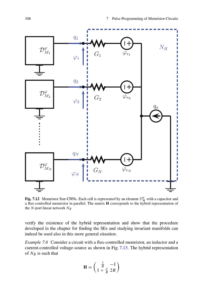
Fig. 7.12 Memristor Star-CNNs. Each cell is represented by an element D
ϕ
M with a capacitor and
a flux-controlled memristor in parallel. The matrix H corresponds to the hybrid representation of
the N -port linear network N R
verify the existence of the hybrid representation and show that the procedure
developed in the chapter for finding the SEs and studying invariant manifolds can
indeed be used also in this more general situation.
Example 7.6 Consider a circuit with a flux-controlled memristor, an inductor and a
current-controlled voltage-source as shown in Fig. 7.13. The hybrid representation
of N R is such that
H =
1
R
−1
1 +
ρ
R 2R
7 Pulse Programming of Memristor Circuits
D
ϕ
M 1
q 1
ϕ 1
G 1
ϕ e 1
D
ϕ
M 2
q 2
ϕ 2
G 2
ϕ e 2
D
ϕ
M N
q N
ϕ N
G N
ϕ e N
q a
N R
Fig. 7.12 Memristor Star-CNNs. Each cell is represented by an element D
ϕ
M with a capacitor and
a flux-controlled memristor in parallel. The matrix H corresponds to the hybrid representation of
the N -port linear network N R
verify the existence of the hybrid representation and show that the procedure
developed in the chapter for finding the SEs and studying invariant manifolds can
indeed be used also in this more general situation.
Example 7.6 Consider a circuit with a flux-controlled memristor, an inductor and a
current-controlled voltage-source as shown in Fig. 7.13. The hybrid representation
of N R is such that
H =
1
R
−1
1 +
ρ
R 2R