

7.2 Motivating Example
273
7.2 Motivating Example
We have seen in Example 2.9 of Chap. 2 how it is possible to set a desired value of
flux or memductance in a flux-controlled memristor by applying a suitable voltage
pulse by means of a battery. This is basically a static example since the memristor
flux remains unchanged once the pulse is over. In the next example, we consider
a simple dynamic memristor circuit and study how it is possible to effectively
programme its dynamics via a pulse generator.
Example 7.1 Consider the simple M − C circuit with a capacitor and a fluxcontrolled memristor q M = f (ϕ M ) studied in Sect. 6.1.2 of Chap. 6. The M − C
circuit has an invariant of motion
Q(t) = Cv C (t) + f (ϕ M (t))
given by the total charge in the circuit. This means that the dynamics of the M − C
circuit evolves on one of the invariant manifolds
M(Q) = {(v C , ϕ M )
T
∈ R
2
: Cv C + f (ϕ M ) = Q}
where Q ∈ R.
Suppose we have v C (t 0 ) = v C 0 and ϕ M (t 0 ) = ϕ M 0 , hence (v C 0 , ϕ M 0 ) T ∈
M(Q 0 ), where Q 0 = Cv C 0 + f (ϕ M 0 ). Consider two instants t 2 > t 1 > t 0 and
suppose we wish that the solution of the M − C circuit evolves on the manifold
M(Q 0 ) in [t 0 , t 1 ], while it evolves on manifold M( ¯
Q) for t ≥ t 2 , where ¯
Q = Q 0 .
This means that we want the solution to switch between the manifolds M(Q 0 ) and
M( ¯
Q) in [t 1 , t 2 ]. This can be achieved in two different ways.
The first possibility is to use additional circuitry and switches in the interval
[t 1 , t 2 ] to set the state (v C (t 2 ), ϕ M (t 2 )) at t 2 in a way that Q(t 2 ) = Cv C (t 2 ) +
f (ϕ M (t 2 )) = ¯
Q. This would require two additional auxiliary networks, one to set
the state v C (t 2 ) of the capacitor and the other to set the state ϕ M (t 2 ) of the memristor,
which is not easy to implement.
There is also a second simpler and more effective way to solve the same problem.
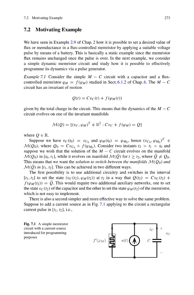
Suppose to add a current source as in Fig. 7.1 applying to the circuit a rectangular
current pulse in [t 1 , t 2 ], i.e.,
Fig. 7.1 A simple memristor
circuit with a current-source
introduced for programming
purposes
273
7.2 Motivating Example
We have seen in Example 2.9 of Chap. 2 how it is possible to set a desired value of
flux or memductance in a flux-controlled memristor by applying a suitable voltage
pulse by means of a battery. This is basically a static example since the memristor
flux remains unchanged once the pulse is over. In the next example, we consider
a simple dynamic memristor circuit and study how it is possible to effectively
programme its dynamics via a pulse generator.
Example 7.1 Consider the simple M − C circuit with a capacitor and a fluxcontrolled memristor q M = f (ϕ M ) studied in Sect. 6.1.2 of Chap. 6. The M − C
circuit has an invariant of motion
Q(t) = Cv C (t) + f (ϕ M (t))
given by the total charge in the circuit. This means that the dynamics of the M − C
circuit evolves on one of the invariant manifolds
M(Q) = {(v C , ϕ M )
T
∈ R
2
: Cv C + f (ϕ M ) = Q}
where Q ∈ R.
Suppose we have v C (t 0 ) = v C 0 and ϕ M (t 0 ) = ϕ M 0 , hence (v C 0 , ϕ M 0 ) T ∈
M(Q 0 ), where Q 0 = Cv C 0 + f (ϕ M 0 ). Consider two instants t 2 > t 1 > t 0 and
suppose we wish that the solution of the M − C circuit evolves on the manifold
M(Q 0 ) in [t 0 , t 1 ], while it evolves on manifold M( ¯
Q) for t ≥ t 2 , where ¯
Q = Q 0 .
This means that we want the solution to switch between the manifolds M(Q 0 ) and
M( ¯
Q) in [t 1 , t 2 ]. This can be achieved in two different ways.
The first possibility is to use additional circuitry and switches in the interval
[t 1 , t 2 ] to set the state (v C (t 2 ), ϕ M (t 2 )) at t 2 in a way that Q(t 2 ) = Cv C (t 2 ) +
f (ϕ M (t 2 )) = ¯
Q. This would require two additional auxiliary networks, one to set
the state v C (t 2 ) of the capacitor and the other to set the state ϕ M (t 2 ) of the memristor,
which is not easy to implement.
There is also a second simpler and more effective way to solve the same problem.
Suppose to add a current source as in Fig. 7.1 applying to the circuit a rectangular
current pulse in [t 1 , t 2 ], i.e.,
Fig. 7.1 A simple memristor
circuit with a current-source
introduced for programming
purposes