

6.3 Third-Order Memristor Chaotic Circuits
253
is an invariant of motion for the SEs in the (v, i)-domain, i.e., the state space R 3 can
be foliated in a continuum of 2D positively invariant manifolds
M(Q 0 ) = {(v C (t), i L (t), ϕ M (t))
T
∈ R
3
: Q(t) = Q 0 }
where Q 0 ∈ R.
On the basis of these formulas, we can study coexisting dynamics and bifurcations without parameters in the circuit along lines similar to the M − L − C circuit.
6.3 Third-Order Memristor Chaotic Circuits
This section focuses on memristor-based oscillators in the class LM that exhibit a
wide range of complex nonlinear dynamical behaviors (e.g., coexistence of stable
EPs, periodic oscillations, and chaotic attractors). In particular, the Memristor-based
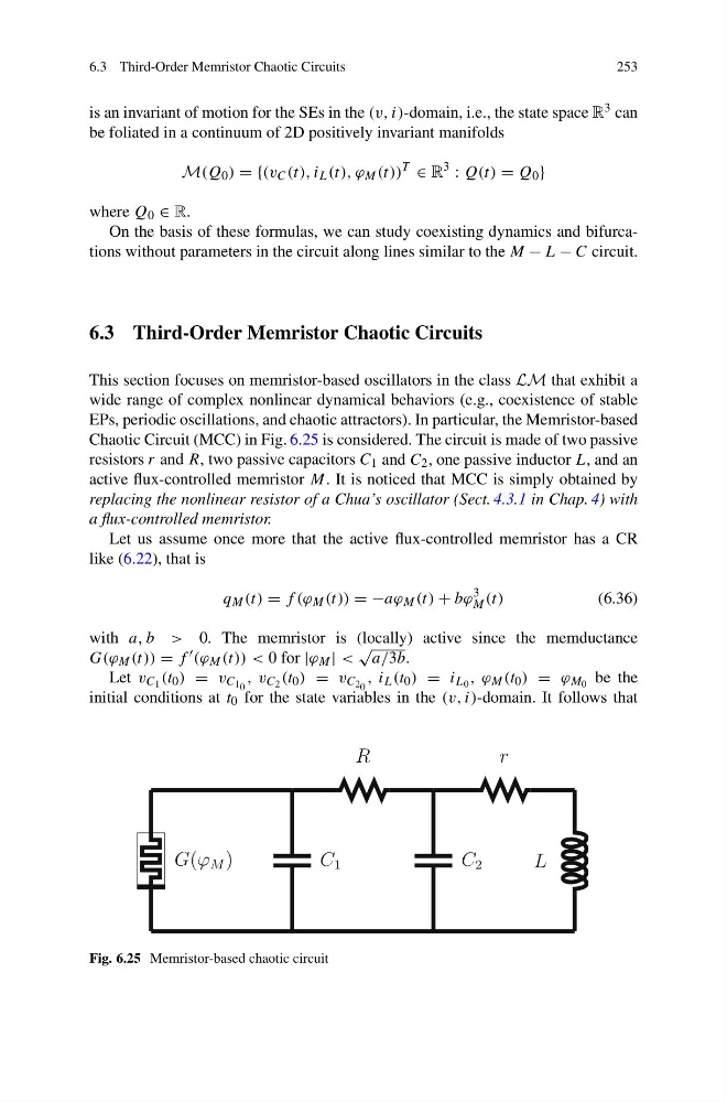
Chaotic Circuit (MCC) in Fig. 6.25 is considered. The circuit is made of two passive
resistors r and R, two passive capacitors C 1 and C 2 , one passive inductor L, and an
active flux-controlled memristor M. It is noticed that MCC is simply obtained by
replacing the nonlinear resistor of a Chua’s oscillator (Sect. 4.3.1 in Chap. 4) with
a flux-controlled memristor.
Let us assume once more that the active flux-controlled memristor has a CR
like (6.22), that is
q M (t) = f (ϕ M (t)) = −aϕ M (t) + bϕ
3
M (t)
(6.36)
with a, b > 0. The memristor is (locally) active since the memductance
G(ϕ M (t)) = f (ϕ M (t)) < 0 for |ϕ M | <
√
a/3b.
Let v C 1 (t 0 ) = v C 1 0 , v C 2 (t 0 ) = v C 2 0 , i L (t 0 ) = i L 0 , ϕ M (t 0 ) = ϕ M 0 be the
initial conditions at t 0 for the state variables in the (v, i)-domain. It follows that
G(ϕ M )
C 1
R
C 2
L
r
Fig. 6.25 Memristor-based chaotic circuit
253
is an invariant of motion for the SEs in the (v, i)-domain, i.e., the state space R 3 can
be foliated in a continuum of 2D positively invariant manifolds
M(Q 0 ) = {(v C (t), i L (t), ϕ M (t))
T
∈ R
3
: Q(t) = Q 0 }
where Q 0 ∈ R.
On the basis of these formulas, we can study coexisting dynamics and bifurcations without parameters in the circuit along lines similar to the M − L − C circuit.
6.3 Third-Order Memristor Chaotic Circuits
This section focuses on memristor-based oscillators in the class LM that exhibit a
wide range of complex nonlinear dynamical behaviors (e.g., coexistence of stable
EPs, periodic oscillations, and chaotic attractors). In particular, the Memristor-based
Chaotic Circuit (MCC) in Fig. 6.25 is considered. The circuit is made of two passive
resistors r and R, two passive capacitors C 1 and C 2 , one passive inductor L, and an
active flux-controlled memristor M. It is noticed that MCC is simply obtained by
replacing the nonlinear resistor of a Chua’s oscillator (Sect. 4.3.1 in Chap. 4) with
a flux-controlled memristor.
Let us assume once more that the active flux-controlled memristor has a CR
like (6.22), that is
q M (t) = f (ϕ M (t)) = −aϕ M (t) + bϕ
3
M (t)
(6.36)
with a, b > 0. The memristor is (locally) active since the memductance
G(ϕ M (t)) = f (ϕ M (t)) < 0 for |ϕ M | <
√
a/3b.
Let v C 1 (t 0 ) = v C 1 0 , v C 2 (t 0 ) = v C 2 0 , i L (t 0 ) = i L 0 , ϕ M (t 0 ) = ϕ M 0 be the
initial conditions at t 0 for the state variables in the (v, i)-domain. It follows that
G(ϕ M )
C 1
R
C 2
L
r
Fig. 6.25 Memristor-based chaotic circuit