

6.1 First-Order Memristor Circuits
223
dv C 1
dt
= −v C 1 − v C 2
(6.5)
dv C 2
dt
= −v C 1 − v C 2 .
(6.6)
It can easily be checked that the circuit has a continuum of non-isolated EPs given
by the line
E = {(v C 1 , v C 2 )
T
∈ R
2
: v C 1 = −v C 2 }.
Also this circuit has an invariant of motion given by
w(v C 1 , v C 2 ) = v C 1 − v C 2 − γ
where γ ∈ R. In fact, differentiating w(·) along the circuit solutions we obtain
˙
w(v C 1 , v C 2 ) =
∂w
∂v C 1
˙
v C 1 +
∂w
∂v C 2
˙
v C 2 = −v C 1 − v C 2 + v C 1 + v C 2 = 0
for any t. Then, there exist ∞ 1 invariant sets for (6.1) given by
M(γ ) = {(v C 1 , v C 2 )
T
∈ R
2
: v C 1 − v C 2 = γ }
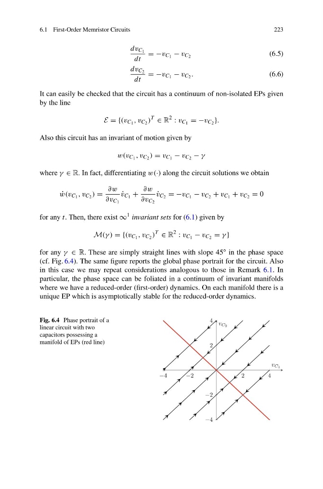
for any γ ∈ R. These are simply straight lines with slope 45
◦ in the phase space
(cf. Fig. 6.4). The same figure reports the global phase portrait for the circuit. Also
in this case we may repeat considerations analogous to those in Remark 6.1. In
particular, the phase space can be foliated in a continuum of invariant manifolds
where we have a reduced-order (first-order) dynamics. On each manifold there is a
unique EP which is asymptotically stable for the reduced-order dynamics.
Fig. 6.4 Phase portrait of a
linear circuit with two
capacitors possessing a
manifold of EPs (red line)
−4
−2
2
4
−4
−2
2
4
v C1
v C2
223
dv C 1
dt
= −v C 1 − v C 2
(6.5)
dv C 2
dt
= −v C 1 − v C 2 .
(6.6)
It can easily be checked that the circuit has a continuum of non-isolated EPs given
by the line
E = {(v C 1 , v C 2 )
T
∈ R
2
: v C 1 = −v C 2 }.
Also this circuit has an invariant of motion given by
w(v C 1 , v C 2 ) = v C 1 − v C 2 − γ
where γ ∈ R. In fact, differentiating w(·) along the circuit solutions we obtain
˙
w(v C 1 , v C 2 ) =
∂w
∂v C 1
˙
v C 1 +
∂w
∂v C 2
˙
v C 2 = −v C 1 − v C 2 + v C 1 + v C 2 = 0
for any t. Then, there exist ∞ 1 invariant sets for (6.1) given by
M(γ ) = {(v C 1 , v C 2 )
T
∈ R
2
: v C 1 − v C 2 = γ }
for any γ ∈ R. These are simply straight lines with slope 45
◦ in the phase space
(cf. Fig. 6.4). The same figure reports the global phase portrait for the circuit. Also
in this case we may repeat considerations analogous to those in Remark 6.1. In
particular, the phase space can be foliated in a continuum of invariant manifolds
where we have a reduced-order (first-order) dynamics. On each manifold there is a
unique EP which is asymptotically stable for the reduced-order dynamics.
Fig. 6.4 Phase portrait of a
linear circuit with two
capacitors possessing a
manifold of EPs (red line)
−4
−2
2
4
−4
−2
2
4
v C1
v C2