

204
5 Flux-Charge Analysis Method of Memristor Circuits
C 1
i C1
+
−
v C1
+
−
v a1
i a1
•
•
•
•
L 1
i L1
−
+
v L1
+
−
v b1
i b1
•
•
•
•
R s
G k (ϕ Mk )
e w (t)
a z (t)
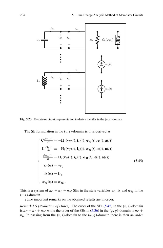
Fig. 5.23 Memristor circuit representation to derive the SEs in the (v, i)-domain
The SE formulation in the (v, i)-domain is thus derived as
⎧
⎪ ⎪ ⎪ ⎪ ⎪ ⎪ ⎪ ⎪ ⎪ ⎪ ⎪ ⎪ ⎪ ⎪ ⎨
⎪ ⎪ ⎪ ⎪ ⎪ ⎪ ⎪ ⎪ ⎪ ⎪ ⎪ ⎪ ⎪ ⎪ ⎩
C
d v C (t)
dt
= −H a (v C (t), i L (t), ϕ M (t), e(t), a(t))
L
d i L (t)
dt
= −H b (v C (t), i L (t), ϕ M (t), e(t), a(t))
d ϕ M (t)
dt
= H c (v C (t), i L (t), ϕ M (t), e(t), a(t))
v C (t 0 ) = v C 0
i L (t 0 ) = i L 0
ϕ M (t 0 ) = ϕ M 0 .
(5.45)
This is a system of n C + n L + n M SEs in the state variables v C , i L and ϕ M in the
(v, i)-domain.
Some important remarks on the obtained results are in order.
Remark 5.9 (Reduction of Order) The order of the SEs (5.45) in the (v, i)-domain
is n C + n L + n M while the order of the SEs in (5.36) in the (ϕ, q)-domain is n C +
n L . In passing from the (v, i)-domain to the (ϕ, q)-domain there is then an order
5 Flux-Charge Analysis Method of Memristor Circuits
C 1
i C1
+
−
v C1
+
−
v a1
i a1
•
•
•
•
L 1
i L1
−
+
v L1
+
−
v b1
i b1
•
•
•
•
R s
G k (ϕ Mk )
e w (t)
a z (t)
Fig. 5.23 Memristor circuit representation to derive the SEs in the (v, i)-domain
The SE formulation in the (v, i)-domain is thus derived as
⎧
⎪ ⎪ ⎪ ⎪ ⎪ ⎪ ⎪ ⎪ ⎪ ⎪ ⎪ ⎪ ⎪ ⎪ ⎨
⎪ ⎪ ⎪ ⎪ ⎪ ⎪ ⎪ ⎪ ⎪ ⎪ ⎪ ⎪ ⎪ ⎪ ⎩
C
d v C (t)
dt
= −H a (v C (t), i L (t), ϕ M (t), e(t), a(t))
L
d i L (t)
dt
= −H b (v C (t), i L (t), ϕ M (t), e(t), a(t))
d ϕ M (t)
dt
= H c (v C (t), i L (t), ϕ M (t), e(t), a(t))
v C (t 0 ) = v C 0
i L (t 0 ) = i L 0
ϕ M (t 0 ) = ϕ M 0 .
(5.45)
This is a system of n C + n L + n M SEs in the state variables v C , i L and ϕ M in the
(v, i)-domain.
Some important remarks on the obtained results are in order.
Remark 5.9 (Reduction of Order) The order of the SEs (5.45) in the (v, i)-domain
is n C + n L + n M while the order of the SEs in (5.36) in the (ϕ, q)-domain is n C +
n L . In passing from the (v, i)-domain to the (ϕ, q)-domain there is then an order