

5.5 Flux-Charge Analysis Method (FCAM) for Class LM of Memristor Circuits
183
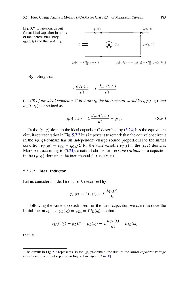
Fig. 5.7 Equivalent circuit
for an ideal capacitor in terms
of the incremental charge
q C (t; t 0 ) and flux ϕ C (t; t 0 )
By noting that
C
dϕ C (t)
dt
= C
dϕ C (t; t 0 )
dt
the CR of the ideal capacitor C in terms of the incremental variables q C (t; t 0 ) and
ϕ C (t; t 0 ) is obtained as
q C (t; t 0 ) = C
dϕ C (t; t 0 )
dt
− q C 0 .
(5.24)
In the (ϕ, q)-domain the ideal capacitor C described by (5.24) has the equivalent
circuit representation in Fig. 5.7. 4 It is important to remark that the equivalent circuit
in the (ϕ, q)-domain has an independent charge source proportional to the initial
condition v C (t 0 ) = v C 0 = q C 0 /C for the state variable v C (t) in the (v, i)-domain.
Moreover, according to (5.24), a natural choice for the state variable of a capacitor
in the (ϕ, q)-domain is the incremental flux ϕ C (t; t 0 ).
5.5.2.2 Ideal Inductor
Let us consider an ideal inductor L described by
ϕ L (t) = Li L (t) = L
dq L (t)
dt
.
Following the same approach used for the ideal capacitor, we can introduce the
initial flux at t 0 , i.e., ϕ L (t 0 ) = ϕ L 0 = Li L (t 0 ), so that
ϕ L (t; t 0 ) = ϕ L (t) − ϕ L (t 0 ) = L
dq L (t)
dt
− Li L (t 0 )
that is
4 The circuit in Fig. 5.7 represents, in the (ϕ, q)-domain, the dual of the initial capacitor voltage
transformation circuit reported in Fig. 2.1 in page 307 in [8].
183
Fig. 5.7 Equivalent circuit
for an ideal capacitor in terms
of the incremental charge
q C (t; t 0 ) and flux ϕ C (t; t 0 )
By noting that
C
dϕ C (t)
dt
= C
dϕ C (t; t 0 )
dt
the CR of the ideal capacitor C in terms of the incremental variables q C (t; t 0 ) and
ϕ C (t; t 0 ) is obtained as
q C (t; t 0 ) = C
dϕ C (t; t 0 )
dt
− q C 0 .
(5.24)
In the (ϕ, q)-domain the ideal capacitor C described by (5.24) has the equivalent
circuit representation in Fig. 5.7. 4 It is important to remark that the equivalent circuit
in the (ϕ, q)-domain has an independent charge source proportional to the initial
condition v C (t 0 ) = v C 0 = q C 0 /C for the state variable v C (t) in the (v, i)-domain.
Moreover, according to (5.24), a natural choice for the state variable of a capacitor
in the (ϕ, q)-domain is the incremental flux ϕ C (t; t 0 ).
5.5.2.2 Ideal Inductor
Let us consider an ideal inductor L described by
ϕ L (t) = Li L (t) = L
dq L (t)
dt
.
Following the same approach used for the ideal capacitor, we can introduce the
initial flux at t 0 , i.e., ϕ L (t 0 ) = ϕ L 0 = Li L (t 0 ), so that
ϕ L (t; t 0 ) = ϕ L (t) − ϕ L (t 0 ) = L
dq L (t)
dt
− Li L (t 0 )
that is
4 The circuit in Fig. 5.7 represents, in the (ϕ, q)-domain, the dual of the initial capacitor voltage
transformation circuit reported in Fig. 2.1 in page 307 in [8].