

282
S. Lupica Spagnolo and B. Daniotti
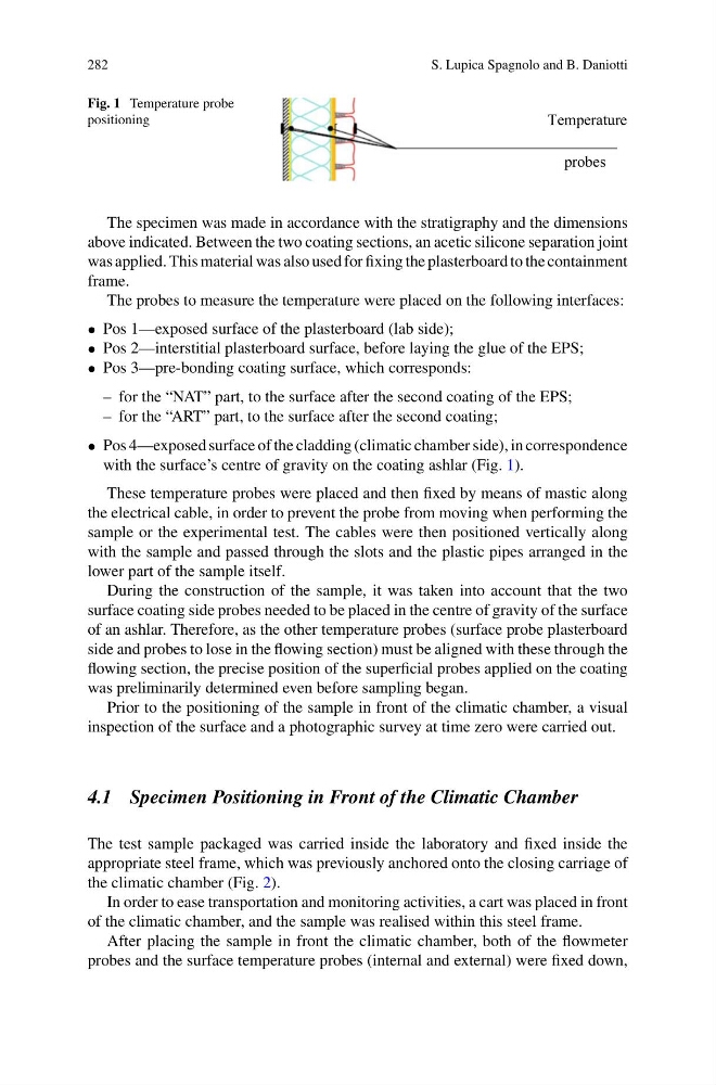
Fig. 1 Temperature probe
positioning
Temperature
probes
The specimen was made in accordance with the stratigraphy and the dimensions
above indicated. Between the two coating sections, an acetic silicone separation joint
was applied. This material was also used for fixing the plasterboard to the containment
frame.
The probes to measure the temperature were placed on the following interfaces:
• Pos 1—exposed surface of the plasterboard (lab side);
• Pos 2—interstitial plasterboard surface, before laying the glue of the EPS;
• Pos 3—pre-bonding coating surface, which corresponds:
– for the “NAT” part, to the surface after the second coating of the EPS;
– for the “ART” part, to the surface after the second coating;
• Pos 4—exposed surface of the cladding (climatic chamber side), in correspondence
with the surface’s centre of gravity on the coating ashlar (Fig. 1).
These temperature probes were placed and then fixed by means of mastic along
the electrical cable, in order to prevent the probe from moving when performing the
sample or the experimental test. The cables were then positioned vertically along
with the sample and passed through the slots and the plastic pipes arranged in the
lower part of the sample itself.
During the construction of the sample, it was taken into account that the two
surface coating side probes needed to be placed in the centre of gravity of the surface
of an ashlar. Therefore, as the other temperature probes (surface probe plasterboard
side and probes to lose in the flowing section) must be aligned with these through the
flowing section, the precise position of the superficial probes applied on the coating
was preliminarily determined even before sampling began.
Prior to the positioning of the sample in front of the climatic chamber, a visual
inspection of the surface and a photographic survey at time zero were carried out.
4.1 Specimen Positioning in Front of the Climatic Chamber
The test sample packaged was carried inside the laboratory and fixed inside the
appropriate steel frame, which was previously anchored onto the closing carriage of
the climatic chamber (Fig. 2).
In order to ease transportation and monitoring activities, a cart was placed in front
of the climatic chamber, and the sample was realised within this steel frame.
After placing the sample in front the climatic chamber, both of the flowmeter
probes and the surface temperature probes (internal and external) were fixed down,
S. Lupica Spagnolo and B. Daniotti
Fig. 1 Temperature probe
positioning
Temperature
probes
The specimen was made in accordance with the stratigraphy and the dimensions
above indicated. Between the two coating sections, an acetic silicone separation joint
was applied. This material was also used for fixing the plasterboard to the containment
frame.
The probes to measure the temperature were placed on the following interfaces:
• Pos 1—exposed surface of the plasterboard (lab side);
• Pos 2—interstitial plasterboard surface, before laying the glue of the EPS;
• Pos 3—pre-bonding coating surface, which corresponds:
– for the “NAT” part, to the surface after the second coating of the EPS;
– for the “ART” part, to the surface after the second coating;
• Pos 4—exposed surface of the cladding (climatic chamber side), in correspondence
with the surface’s centre of gravity on the coating ashlar (Fig. 1).
These temperature probes were placed and then fixed by means of mastic along
the electrical cable, in order to prevent the probe from moving when performing the
sample or the experimental test. The cables were then positioned vertically along
with the sample and passed through the slots and the plastic pipes arranged in the
lower part of the sample itself.
During the construction of the sample, it was taken into account that the two
surface coating side probes needed to be placed in the centre of gravity of the surface
of an ashlar. Therefore, as the other temperature probes (surface probe plasterboard
side and probes to lose in the flowing section) must be aligned with these through the
flowing section, the precise position of the superficial probes applied on the coating
was preliminarily determined even before sampling began.
Prior to the positioning of the sample in front of the climatic chamber, a visual
inspection of the surface and a photographic survey at time zero were carried out.
4.1 Specimen Positioning in Front of the Climatic Chamber
The test sample packaged was carried inside the laboratory and fixed inside the
appropriate steel frame, which was previously anchored onto the closing carriage of
the climatic chamber (Fig. 2).
In order to ease transportation and monitoring activities, a cart was placed in front
of the climatic chamber, and the sample was realised within this steel frame.
After placing the sample in front the climatic chamber, both of the flowmeter
probes and the surface temperature probes (internal and external) were fixed down,