

1.7 Active Dipolar Rollers
21
therefore unable to catch up and coalesce. Finally, at a still higher packing, the entire
system solidifies. Snapshots (upper row) and plots of the average roller velocities
and densities (lower row) in different regimes are shown in Fig. 1.16c.
When running the same rollers in a circular corral (Bricard et al, 2015), another
pattern was observed, namely, a vortex occupying the entire enclosure with a higher
density at the periphery (Fig. 1.17d). The same pattern came about in simulations
of collective dynamics (Fig. 1.17b) at higher densities and when the values of the
exclusion range b (see Fig. 1.15) were substantially larger than the particle radius
a. At lower ratios b/a, a swarm cruising around the circular corral (Fig. 1.17c) is
seen instead of a vortex, and as usual, there is a disordered gas at low densities
(Fig. 1.17a).
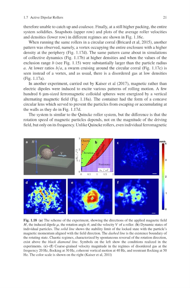
In another experiment, carried out by Kaiser et al (2017), magnetic rather than
electric dipoles were induced to excite various patterns of rolling motion. A few
hundred 6 μm-sized ferromagnetic colloidal spheres were energized by a vertical
alternating magnetic field (Fig. 1.18a). The container had the form of a concave
circular lens which served to prevent the particles from escaping or accumulating at
the walls as they do in Fig. 1.17d.
The system is similar to the Quincke roller system, but the difference is that the
rotation speed of magnetic particles depends, not on the magnitude of the driving
field, but only on its frequency. Unlike Quincke rollers, even individual ferromagnetic
Fig. 1.18 (a) The scheme of the experiment, showing the directions of the applied magnetic field
H, the induced dipole μ, the rotation angle θ, and the velocity V of a roller. (b) Dynamic states of
individual particles. The solid line shows the stability limit of the locked state with the particle’s
magnetic momentum aligned with the field direction. The dashed line is the existence boundary of
the rotating state. Chaotic regimes, characterized by spontaneous reversal of the rotation direction,
exist above the black diamond line. Symbols on the left show the conditions realized in the
experiments. (c)–(f) Coarse-grained velocity magnitude in the regimes of disordered gas at the
frequency 20 Hz, flocking at 30 Hz, coherent vortical motion at 40 Hz, and reentrant flocking at 50
Hz. The color scale is shown on the right (Kaiser et al, 201l)
21
therefore unable to catch up and coalesce. Finally, at a still higher packing, the entire
system solidifies. Snapshots (upper row) and plots of the average roller velocities
and densities (lower row) in different regimes are shown in Fig. 1.16c.
When running the same rollers in a circular corral (Bricard et al, 2015), another
pattern was observed, namely, a vortex occupying the entire enclosure with a higher
density at the periphery (Fig. 1.17d). The same pattern came about in simulations
of collective dynamics (Fig. 1.17b) at higher densities and when the values of the
exclusion range b (see Fig. 1.15) were substantially larger than the particle radius
a. At lower ratios b/a, a swarm cruising around the circular corral (Fig. 1.17c) is
seen instead of a vortex, and as usual, there is a disordered gas at low densities
(Fig. 1.17a).
In another experiment, carried out by Kaiser et al (2017), magnetic rather than
electric dipoles were induced to excite various patterns of rolling motion. A few
hundred 6 μm-sized ferromagnetic colloidal spheres were energized by a vertical
alternating magnetic field (Fig. 1.18a). The container had the form of a concave
circular lens which served to prevent the particles from escaping or accumulating at
the walls as they do in Fig. 1.17d.
The system is similar to the Quincke roller system, but the difference is that the
rotation speed of magnetic particles depends, not on the magnitude of the driving
field, but only on its frequency. Unlike Quincke rollers, even individual ferromagnetic
Fig. 1.18 (a) The scheme of the experiment, showing the directions of the applied magnetic field
H, the induced dipole μ, the rotation angle θ, and the velocity V of a roller. (b) Dynamic states of
individual particles. The solid line shows the stability limit of the locked state with the particle’s
magnetic momentum aligned with the field direction. The dashed line is the existence boundary of
the rotating state. Chaotic regimes, characterized by spontaneous reversal of the rotation direction,
exist above the black diamond line. Symbols on the left show the conditions realized in the
experiments. (c)–(f) Coarse-grained velocity magnitude in the regimes of disordered gas at the
frequency 20 Hz, flocking at 30 Hz, coherent vortical motion at 40 Hz, and reentrant flocking at 50
Hz. The color scale is shown on the right (Kaiser et al, 201l)