

8 Fréedericksz-Like Positional Transition Triggered by An External Electric Field
341
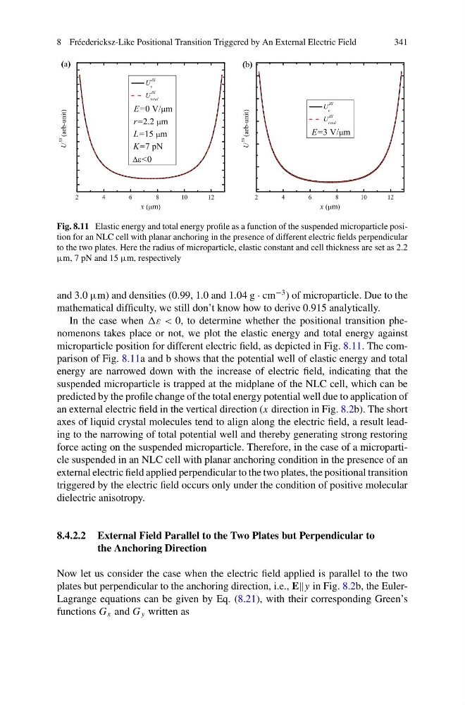
Fig. 8.11 Elastic energy and total energy profile as a function of the suspended microparticle position for an NLC cell with planar anchoring in the presence of different electric fields perpendicular
to the two plates. Here the radius of microparticle, elastic constant and cell thickness are set as 2.2
µm, 7 pN and 15 µm, respectively
and 3.0 µm) and densities (0.99, 1.0 and 1.04 g · cm
−3 ) of microparticle. Due to the
mathematical difficulty, we still don’t know how to derive 0.915 analytically.
In the case when ε < 0, to determine whether the positional transition phenomenons takes place or not, we plot the elastic energy and total energy against
microparticle position for different electric field, as depicted in Fig. 8.11. The comparison of Fig. 8.11a and b shows that the potential well of elastic energy and total
energy are narrowed down with the increase of electric field, indicating that the
suspended microparticle is trapped at the midplane of the NLC cell, which can be
predicted by the profile change of the total energy potential well due to application of
an external electric field in the vertical direction (x direction in Fig. 8.2b). The short
axes of liquid crystal molecules tend to align along the electric field, a result leading to the narrowing of total potential well and thereby generating strong restoring
force acting on the suspended microparticle. Therefore, in the case of a microparticle suspended in an NLC cell with planar anchoring condition in the presence of an
external electric field applied perpendicular to the two plates, the positional transition
triggered by the electric field occurs only under the condition of positive molecular
dielectric anisotropy.
8.4.2.2 External Field Parallel to the Two Plates but Perpendicular to
the Anchoring Direction
Now let us consider the case when the electric field applied is parallel to the two
plates but perpendicular to the anchoring direction, i.e., E in Fig. 8.2b, the EulerLagrange equations can be given by Eq. (8.21), with their corresponding Green’s
functions G x and G y written as
341
Fig. 8.11 Elastic energy and total energy profile as a function of the suspended microparticle position for an NLC cell with planar anchoring in the presence of different electric fields perpendicular
to the two plates. Here the radius of microparticle, elastic constant and cell thickness are set as 2.2
µm, 7 pN and 15 µm, respectively
and 3.0 µm) and densities (0.99, 1.0 and 1.04 g · cm
−3 ) of microparticle. Due to the
mathematical difficulty, we still don’t know how to derive 0.915 analytically.
In the case when ε < 0, to determine whether the positional transition phenomenons takes place or not, we plot the elastic energy and total energy against
microparticle position for different electric field, as depicted in Fig. 8.11. The comparison of Fig. 8.11a and b shows that the potential well of elastic energy and total
energy are narrowed down with the increase of electric field, indicating that the
suspended microparticle is trapped at the midplane of the NLC cell, which can be
predicted by the profile change of the total energy potential well due to application of
an external electric field in the vertical direction (x direction in Fig. 8.2b). The short
axes of liquid crystal molecules tend to align along the electric field, a result leading to the narrowing of total potential well and thereby generating strong restoring
force acting on the suspended microparticle. Therefore, in the case of a microparticle suspended in an NLC cell with planar anchoring condition in the presence of an
external electric field applied perpendicular to the two plates, the positional transition
triggered by the electric field occurs only under the condition of positive molecular
dielectric anisotropy.
8.4.2.2 External Field Parallel to the Two Plates but Perpendicular to
the Anchoring Direction
Now let us consider the case when the electric field applied is parallel to the two
plates but perpendicular to the anchoring direction, i.e., E in Fig. 8.2b, the EulerLagrange equations can be given by Eq. (8.21), with their corresponding Green’s
functions G x and G y written as