

6.6 The Influence of Wall Material on Brass Instrument Performance
321
40
30
20
10
0
-10
-20
0
100
200
300
400
500
600
700
800
900
1000
Frequency (Hz)
(a)
(b)
(c)
|Z| (dB)
|Z| (dB)
18
16
14
12
10
760
780
800
820
Frequency (Hz)
Frequency (Hz)
Intertance (dB)
50
40
30
20
10
0
760
780
800
820
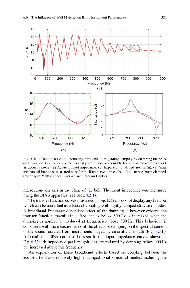
Fig. 6.31 A modification of a boundary limit condition (adding damping by clamping the brace
of a trombone) suppresses a mechanical piston mode responsible for a coincidence effect with
an acoustic mode. (a) Acoustic input impedance. (b) Expansion of dotted area in (a). (c) Axial
mechanical inertance measured at bell rim. Blue curves: brace free. Red curves: brace clamped.
Courtesy of Mathieu Sécail-Géraud and François Gautier
microphone on axis in the plane of the bell. The input impedance was measured
using the BIAS apparatus (see Sect. 4.2.1).
The transfer function curves illustrated in Fig. 6.32a, b do not display any features
which can be identified as effects of coupling with lightly damped structural modes.
A broadband frequency-dependent effect of the damping is however evident: the
transfer function magnitude at frequencies below 500 Hz is increased when the
damping is applied but reduced at frequencies above 500 Hz. This behaviour is
consistent with the measurements of the effects of damping on the spectral content
of the sound radiated from instruments played by an artificial mouth (Fig. 6.24b).
A broadband effect can also be seen in the input impedance curves shown in
Fig. 6.32c, d: impedance peak magnitudes are reduced by damping below 900 Hz
but increased above this frequency.
An explanation of these broadband effects based on coupling between the
acoustic field and relatively highly damped axial structural modes, including the
321
40
30
20
10
0
-10
-20
0
100
200
300
400
500
600
700
800
900
1000
Frequency (Hz)
(a)
(b)
(c)
|Z| (dB)
|Z| (dB)
18
16
14
12
10
760
780
800
820
Frequency (Hz)
Frequency (Hz)
Intertance (dB)
50
40
30
20
10
0
760
780
800
820
Fig. 6.31 A modification of a boundary limit condition (adding damping by clamping the brace
of a trombone) suppresses a mechanical piston mode responsible for a coincidence effect with
an acoustic mode. (a) Acoustic input impedance. (b) Expansion of dotted area in (a). (c) Axial
mechanical inertance measured at bell rim. Blue curves: brace free. Red curves: brace clamped.
Courtesy of Mathieu Sécail-Géraud and François Gautier
microphone on axis in the plane of the bell. The input impedance was measured
using the BIAS apparatus (see Sect. 4.2.1).
The transfer function curves illustrated in Fig. 6.32a, b do not display any features
which can be identified as effects of coupling with lightly damped structural modes.
A broadband frequency-dependent effect of the damping is however evident: the
transfer function magnitude at frequencies below 500 Hz is increased when the
damping is applied but reduced at frequencies above 500 Hz. This behaviour is
consistent with the measurements of the effects of damping on the spectral content
of the sound radiated from instruments played by an artificial mouth (Fig. 6.24b).
A broadband effect can also be seen in the input impedance curves shown in
Fig. 6.32c, d: impedance peak magnitudes are reduced by damping below 900 Hz
but increased above this frequency.
An explanation of these broadband effects based on coupling between the
acoustic field and relatively highly damped axial structural modes, including the