

512
15 System Testing and Validation Technology of Lunar Lander
Propellant supply
and gauge system
Pre-evacuation
system
Monitor system
Gas supply
system
Vacuum test chamber
Ejection pipeline
Engine Testbed
Ejection
system
7500N
Throttling engine
Engine control signal
Thrust measurement
system
Power supply
Adapter box
Throttling control system
Thrust voltage analog
Thrust measuarement
Valve control
Gas
Supply
Valve
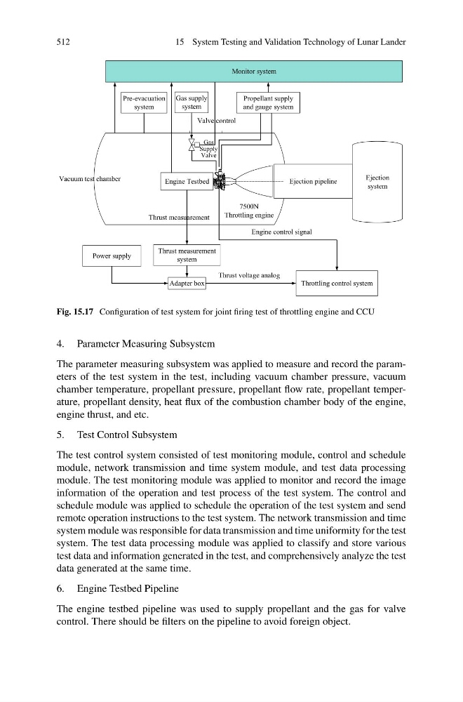
Fig. 15.17 Configuration of test system for joint firing test of throttling engine and CCU
4. Parameter Measuring Subsystem
The parameter measuring subsystem was applied to measure and record the parameters of the test system in the test, including vacuum chamber pressure, vacuum
chamber temperature, propellant pressure, propellant flow rate, propellant temperature, propellant density, heat flux of the combustion chamber body of the engine,
engine thrust, and etc.
5. Test Control Subsystem
The test control system consisted of test monitoring module, control and schedule
module, network transmission and time system module, and test data processing
module. The test monitoring module was applied to monitor and record the image
information of the operation and test process of the test system. The control and
schedule module was applied to schedule the operation of the test system and send
remote operation instructions to the test system. The network transmission and time
system module was responsible for data transmission and time uniformity for the test
system. The test data processing module was applied to classify and store various
test data and information generated in the test, and comprehensively analyze the test
data generated at the same time.
6. Engine Testbed Pipeline
The engine testbed pipeline was used to supply propellant and the gas for valve
control. There should be filters on the pipeline to avoid foreign object.
15 System Testing and Validation Technology of Lunar Lander
Propellant supply
and gauge system
Pre-evacuation
system
Monitor system
Gas supply
system
Vacuum test chamber
Ejection pipeline
Engine Testbed
Ejection
system
7500N
Throttling engine
Engine control signal
Thrust measurement
system
Power supply
Adapter box
Throttling control system
Thrust voltage analog
Thrust measuarement
Valve control
Gas
Supply
Valve
Fig. 15.17 Configuration of test system for joint firing test of throttling engine and CCU
4. Parameter Measuring Subsystem
The parameter measuring subsystem was applied to measure and record the parameters of the test system in the test, including vacuum chamber pressure, vacuum
chamber temperature, propellant pressure, propellant flow rate, propellant temperature, propellant density, heat flux of the combustion chamber body of the engine,
engine thrust, and etc.
5. Test Control Subsystem
The test control system consisted of test monitoring module, control and schedule
module, network transmission and time system module, and test data processing
module. The test monitoring module was applied to monitor and record the image
information of the operation and test process of the test system. The control and
schedule module was applied to schedule the operation of the test system and send
remote operation instructions to the test system. The network transmission and time
system module was responsible for data transmission and time uniformity for the test
system. The test data processing module was applied to classify and store various
test data and information generated in the test, and comprehensively analyze the test
data generated at the same time.
6. Engine Testbed Pipeline
The engine testbed pipeline was used to supply propellant and the gas for valve
control. There should be filters on the pipeline to avoid foreign object.