

14.5 Ground Test System
475
Lunar Lander
Lunar Rover
Telemetry front-end
equipment
Data Transmission frontend equipment
Telecommand front-end
equipment
Integrated Electronic
Subsystem test equipment
Data Transmission frontend equipment
Telecommand front-end
equipment
Real-Time data Server
(RTS)
Main Test Processor
(MTP)
Database Storage Server
(DBS)
Data Judgement Server
(DJS)
Subsystem Test
Software
Test Terminal
Test Terminal
Test Terminal
Test Terminal
Test Terminal
Database
(Oracle)
X Band telemetry 1
X Band telemetry 2
S Band telemetry
Video wired
telemetry
X band data
transmission
X Band telecomm. 1
X Band telecomm. 2
S Band telecomm.
RS-422
telemetry
RS-422 telecomm.
X band telemetry
and data
transmission
X Band telecomm.
1
X Band telecomm. 2
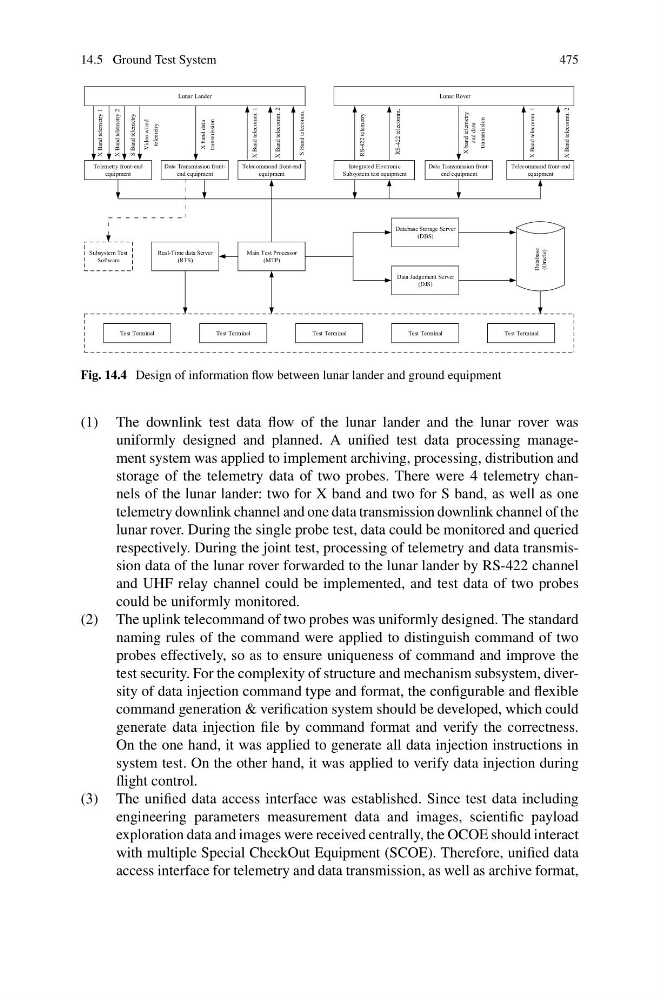
Fig. 14.4 Design of information flow between lunar lander and ground equipment
(1) The downlink test data flow of the lunar lander and the lunar rover was
uniformly designed and planned. A unified test data processing management system was applied to implement archiving, processing, distribution and
storage of the telemetry data of two probes. There were 4 telemetry channels of the lunar lander: two for X band and two for S band, as well as one
telemetry downlink channel and one data transmission downlink channel of the
lunar rover. During the single probe test, data could be monitored and queried
respectively. During the joint test, processing of telemetry and data transmission data of the lunar rover forwarded to the lunar lander by RS-422 channel
and UHF relay channel could be implemented, and test data of two probes
could be uniformly monitored.
(2) The uplink telecommand of two probes was uniformly designed. The standard
naming rules of the command were applied to distinguish command of two
probes effectively, so as to ensure uniqueness of command and improve the
test security. For the complexity of structure and mechanism subsystem, diversity of data injection command type and format, the configurable and flexible
command generation & verification system should be developed, which could
generate data injection file by command format and verify the correctness.
On the one hand, it was applied to generate all data injection instructions in
system test. On the other hand, it was applied to verify data injection during
flight control.
(3) The unified data access interface was established. Since test data including
engineering parameters measurement data and images, scientific payload
exploration data and images were received centrally, the OCOE should interact
with multiple Special CheckOut Equipment (SCOE). Therefore, unified data
access interface for telemetry and data transmission, as well as archive format,
475
Lunar Lander
Lunar Rover
Telemetry front-end
equipment
Data Transmission frontend equipment
Telecommand front-end
equipment
Integrated Electronic
Subsystem test equipment
Data Transmission frontend equipment
Telecommand front-end
equipment
Real-Time data Server
(RTS)
Main Test Processor
(MTP)
Database Storage Server
(DBS)
Data Judgement Server
(DJS)
Subsystem Test
Software
Test Terminal
Test Terminal
Test Terminal
Test Terminal
Test Terminal
Database
(Oracle)
X Band telemetry 1
X Band telemetry 2
S Band telemetry
Video wired
telemetry
X band data
transmission
X Band telecomm. 1
X Band telecomm. 2
S Band telecomm.
RS-422
telemetry
RS-422 telecomm.
X band telemetry
and data
transmission
X Band telecomm.
1
X Band telecomm. 2
Fig. 14.4 Design of information flow between lunar lander and ground equipment
(1) The downlink test data flow of the lunar lander and the lunar rover was
uniformly designed and planned. A unified test data processing management system was applied to implement archiving, processing, distribution and
storage of the telemetry data of two probes. There were 4 telemetry channels of the lunar lander: two for X band and two for S band, as well as one
telemetry downlink channel and one data transmission downlink channel of the
lunar rover. During the single probe test, data could be monitored and queried
respectively. During the joint test, processing of telemetry and data transmission data of the lunar rover forwarded to the lunar lander by RS-422 channel
and UHF relay channel could be implemented, and test data of two probes
could be uniformly monitored.
(2) The uplink telecommand of two probes was uniformly designed. The standard
naming rules of the command were applied to distinguish command of two
probes effectively, so as to ensure uniqueness of command and improve the
test security. For the complexity of structure and mechanism subsystem, diversity of data injection command type and format, the configurable and flexible
command generation & verification system should be developed, which could
generate data injection file by command format and verify the correctness.
On the one hand, it was applied to generate all data injection instructions in
system test. On the other hand, it was applied to verify data injection during
flight control.
(3) The unified data access interface was established. Since test data including
engineering parameters measurement data and images, scientific payload
exploration data and images were received centrally, the OCOE should interact
with multiple Special CheckOut Equipment (SCOE). Therefore, unified data
access interface for telemetry and data transmission, as well as archive format,