

470
14 Electrical Testing Technology of Lunar Lander
14.4.3 Design of Test Coverage
To verify the correctness of the function and performance of the lunar lander, the test
coverage should be fully designed to ensure that instruments, subsystem, lunar lander
system and interfaces to other engineering systems should meet the requirements.
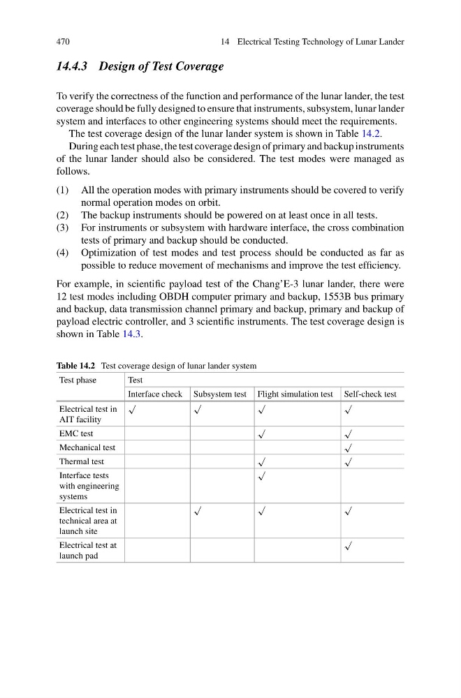
The test coverage design of the lunar lander system is shown in Table 14.2.
During each test phase, the test coverage design of primary and backup instruments
of the lunar lander should also be considered. The test modes were managed as
follows.
(1) All the operation modes with primary instruments should be covered to verify
normal operation modes on orbit.
(2) The backup instruments should be powered on at least once in all tests.
(3) For instruments or subsystem with hardware interface, the cross combination
tests of primary and backup should be conducted.
(4) Optimization of test modes and test process should be conducted as far as
possible to reduce movement of mechanisms and improve the test efficiency.
For example, in scientific payload test of the Chang’E-3 lunar lander, there were
12 test modes including OBDH computer primary and backup, 1553B bus primary
and backup, data transmission channel primary and backup, primary and backup of
payload electric controller, and 3 scientific instruments. The test coverage design is
shown in Table 14.3.
Table 14.2 Test coverage design of lunar lander system
Test phase
Test
Interface check Subsystem test Flight simulation test Self-check test
Electrical test in
AIT facility
√
√
√
√
EMC test
√
√
Mechanical test
√
Thermal test
√
√
Interface tests
with engineering
systems
√
Electrical test in
technical area at
launch site
√
√
√
Electrical test at
launch pad
√
14 Electrical Testing Technology of Lunar Lander
14.4.3 Design of Test Coverage
To verify the correctness of the function and performance of the lunar lander, the test
coverage should be fully designed to ensure that instruments, subsystem, lunar lander
system and interfaces to other engineering systems should meet the requirements.
The test coverage design of the lunar lander system is shown in Table 14.2.
During each test phase, the test coverage design of primary and backup instruments
of the lunar lander should also be considered. The test modes were managed as
follows.
(1) All the operation modes with primary instruments should be covered to verify
normal operation modes on orbit.
(2) The backup instruments should be powered on at least once in all tests.
(3) For instruments or subsystem with hardware interface, the cross combination
tests of primary and backup should be conducted.
(4) Optimization of test modes and test process should be conducted as far as
possible to reduce movement of mechanisms and improve the test efficiency.
For example, in scientific payload test of the Chang’E-3 lunar lander, there were
12 test modes including OBDH computer primary and backup, 1553B bus primary
and backup, data transmission channel primary and backup, primary and backup of
payload electric controller, and 3 scientific instruments. The test coverage design is
shown in Table 14.3.
Table 14.2 Test coverage design of lunar lander system
Test phase
Test
Interface check Subsystem test Flight simulation test Self-check test
Electrical test in
AIT facility
√
√
√
√
EMC test
√
√
Mechanical test
√
Thermal test
√
√
Interface tests
with engineering
systems
√
Electrical test in
technical area at
launch site
√
√
√
Electrical test at
launch pad
√