

12.5 Typical Application of System Integration and Assembly
421
There are two types of solar arrays in the assembly of spacecraft. The body-mounted
solar array is installed on the outer surface of spacecraft, while the surface may be in
shape of sphere, polyhedron and cylindrical. Such assembly method is the simplest
and there is no moving part, therefore it is more reliable. The deployable solar array is
connected with spacecraft, but is independent of the spacecraft body. During launch,
the deployable solar array is folded in the spacecraft or on lateral plate. After orbit
injection, it can be deployed. The assembly of deployable solar array needs help of
air-floating and suspension for simulation of zero-gravity. In case of one-dimensional
deployment, generally suspension is applied, while air-floating is applied to simulate
zero gravity for dual or multiple dimension deployment.
There were both body-mounted and deployable solar panels on the Chang’E-3
lunar lander. When the body-mounted solar panel was assembled, the focus was
insulation. The deployable solar panels were driven by motor to implement onedimension deployment with high assembly accuracy requirements. Special attention
should be paid to assembly accuracy and movable cables in the assembly process.
(1) Accuracy of solar panel assembly. When the solar panel was assembled, the
output shaft of the reducer should be aligned with the rotation axis of the hinge
after the drive mechanism (motor, reducer and transmission arm) was assembled,
and the error of the shaft should be less than 0.15 mm. The deployment suspension
method was applied to achieve low gravity environment in assembly of solar panel.
Then the dual-axis turntable was applied to adjust the attitude of the lunar lander.
Real time monitoring was implemented by measurement to ensure the assembly
relationship and accuracy requirements between the lunar lander and the solar panel.
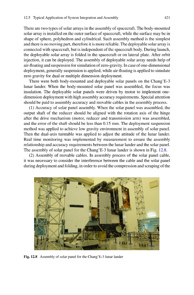
The assembly of solar panel for the Chang’E-3 lunar lander is shown in Fig. 12.8.
(2) Assembly of movable cables. In assembly process of the solar panel cable,
it was necessary to consider the interference between the cable and the solar panel
during deployment and folding, in order to avoid the compression and scraping of the
Fig. 12.8 Assembly of solar panel for the Chang’E-3 lunar lander
421
There are two types of solar arrays in the assembly of spacecraft. The body-mounted
solar array is installed on the outer surface of spacecraft, while the surface may be in
shape of sphere, polyhedron and cylindrical. Such assembly method is the simplest
and there is no moving part, therefore it is more reliable. The deployable solar array is
connected with spacecraft, but is independent of the spacecraft body. During launch,
the deployable solar array is folded in the spacecraft or on lateral plate. After orbit
injection, it can be deployed. The assembly of deployable solar array needs help of
air-floating and suspension for simulation of zero-gravity. In case of one-dimensional
deployment, generally suspension is applied, while air-floating is applied to simulate
zero gravity for dual or multiple dimension deployment.
There were both body-mounted and deployable solar panels on the Chang’E-3
lunar lander. When the body-mounted solar panel was assembled, the focus was
insulation. The deployable solar panels were driven by motor to implement onedimension deployment with high assembly accuracy requirements. Special attention
should be paid to assembly accuracy and movable cables in the assembly process.
(1) Accuracy of solar panel assembly. When the solar panel was assembled, the
output shaft of the reducer should be aligned with the rotation axis of the hinge
after the drive mechanism (motor, reducer and transmission arm) was assembled,
and the error of the shaft should be less than 0.15 mm. The deployment suspension
method was applied to achieve low gravity environment in assembly of solar panel.
Then the dual-axis turntable was applied to adjust the attitude of the lunar lander.
Real time monitoring was implemented by measurement to ensure the assembly
relationship and accuracy requirements between the lunar lander and the solar panel.
The assembly of solar panel for the Chang’E-3 lunar lander is shown in Fig. 12.8.
(2) Assembly of movable cables. In assembly process of the solar panel cable,
it was necessary to consider the interference between the cable and the solar panel
during deployment and folding, in order to avoid the compression and scraping of the
Fig. 12.8 Assembly of solar panel for the Chang’E-3 lunar lander